Toyota Sienna Service Manual: Removal
1. REMOVE V-BANK COVER SUB-ASSEMBLY (See page EM-28) 2. REMOVE NO. 1 ENGINE UNDER COVER (See page EM-26) 3. DRAIN ENGINE COOLANT (See page CO-6) 4. REMOVE FRONT WHEEL RH 5. REMOVE FRONT FENDER APRON SEAL RH 6. REMOVE V-RIBBED BELT (See page EM-6) 7. DISCONNECT NO. 2 RADIATOR HOSE
(a) Disconnect the No. 2 radiator hose from the engine.
8. REMOVE NO. 2 IDLER PULLEY SUB-ASSEMBLY
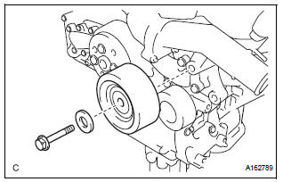
(a) Remove the bolt, idler pulley cover plate and idler pulley sub-assembly.
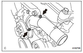
9. REMOVE WATER INLET
(a) Remove the 2 nuts and water inlet.
10. REMOVE THERMOSTAT
(a) Remove the gasket from the thermostat.
 Thermostat
Components
...
 Inspection
1. INSPECT THERMOSTAT
(a) Inspect the thermostat.
HINT:
The valve opening temperature is inscribed on the
thermostat.
(b) Immerse the thermostat in water and gradually heat
the water.
...
Other materials:
Diagnosis system
1. CHECK DLC3
The ECU uses ISO 15765-4 for communication.
The terminal arrangement of the DLC3 complies
with SAE J1962 and meets the ISO 15765-4 format.
NOTICE:
*: Before measuring the resistance, leave the
vehicle as is for at least 1 minute and do not
operate the igniti ...
Reassembly
1. INSTALL BACK DOOR STOPPER LOWER
Install the 2 stoppers with the 4 bolts.
Torque: 7.0 N*m (71 kgf*cm, 62 in.*lbf)
2. INSTALL BACK DOOR BASE STOPPER BRACKET
Install the 2 stopper brackets with the 4 bolts.
Torque: 7.0 N*m (71 kgf*cm, 62 in.*lbf)
3. INSTALL BACK DOOR LOCK ASSEMBLY
...
Canceling the power sliding door system (vehicles with power
sliding doors)
Turn the main switch off to disable
the power sliding door system.
Off
The sliding doors can only be
opened and closed manually.
On*
The power sliding door can be
opened and closed with the power
sliding door switches for the front
occupants or wireless remote control
even if ...
