Toyota Sienna Service Manual: Throttle / Pedal Position Sensor/ Switch
DTC P2120 Throttle / Pedal Position Sensor / Switch "D" Circuit
DTC P2122 Throttle / Pedal Position Sensor / Switch "D" Circuit Low Input
DTC P2123 Throttle / Pedal Position Sensor / Switch "D" Circuit High Input
DTC P2125 Throttle / Pedal Position Sensor / Switch "E" Circuit
DTC P2127 Throttle / Pedal Position Sensor / Switch "E" Circuit Low Input
DTC P2128 Throttle / Pedal Position Sensor / Switch "E" Circuit High Input
DTC P2138 Throttle / Pedal Position Sensor / Switch "D" / "E" Voltage Correlation
HINT: These DTCs relate to the Accelerator Pedal Position (APP) sensor.
DESCRIPTION
HINT: This ETCS (Electronic Throttle Control System) does not use a throttle cable.
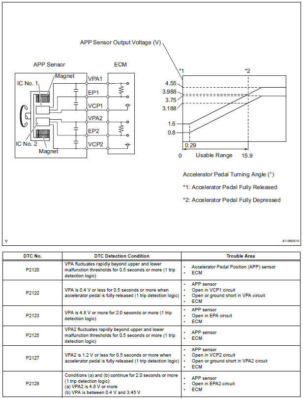
The Accelerator Pedal Position (APP) sensor is integrated with the accelerator pedal bracket and has 2 sensor circuits: VPA (main) and VPA2 (sub). This sensor is a non-contact type, and uses Hall-effect elements, in order to yield accurate signals, even in extreme driving conditions, such as at high speeds as well as very low speeds. The voltage, which is applied to terminals VPA and VPA2 of the ECM, varies between 0 V and 5 V in proportion to the operating angle of the accelerator pedal (throttle valve). A signal from VPA indicates the actual accelerator pedal opening angle (throttle valve opening angle) and is used for engine control. A signal from VPA2 conveys the status of the VPA circuit and is used to check the APP sensor itself.
The ECM monitors the actual accelerator pedal opening angle (throttle valve opening angle) through the signals from VPA and VPA2, and controls the throttle actuator according to these signals.

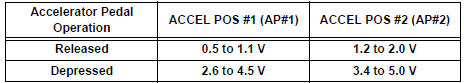
HINT: When any of these DTCs are set, check the APP sensor voltage by selecting the following menu items on the intelligent tester: DIAGNOSIS / ENHANCED OBD II / DATA LIST / PRIMARY / ACCEL POS #1 and ACCEL POS #2.
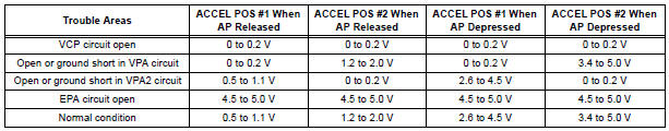
HINT:
- Accelerator pedal positions are expressed as voltages.
- AP denotes Accelerator Pedal.
MONITOR DESCRIPTION
When either of the voltage outputs of VPA or VPA2 deviates from the standard range, or the difference between the voltage outputs of the 2 sensor circuits is less than the threshold, the ECM determines that there is a malfunction in the APP sensor. The ECM then illuminates the MIL and sets a DTC.
Example: When the voltage output of VPA drops below 0.4 V for more than 0.5 seconds when the accelerator pedal is fully depressed, DTC P2122 is set.
If the malfunction is not repaired successfully, a DTC is set 2 seconds after the engine is next started.
MONITOR STRATEGY
TYPICAL ENABLING CONDITIONS

TYPICAL MALFUNCTION THRESHOLDS
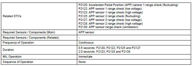
P2120:

P2122:

P2123:

P2125:

P2127:

P2128:

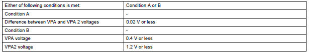
P2138:
COMPONENT OPERATING RANGE
FAIL-SAFE
When any of DTCs P2120, P2121, P2122, P2123, P2125, P2127, P2128 and P2138 are set, the ECM enters fail-safe mode. If either of the 2 sensor circuits malfunctions, the ECM uses the remaining circuit to calculate the accelerator pedal position to allow the vehicle to continue driving. If both of the circuits malfunction, the ECM regards the accelerator pedal as being released. As a result, the throttle valve is closed and the engine idles.
Fail-safe mode continues until a pass condition is detected, and the ignition switch is turned off.
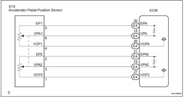
WIRING DIAGRAM
INSPECTION PROCEDURE
HINT: Read freeze frame data using the intelligent tester. The ECM records vehicle and driving condition information as freeze frame data the moment a DTC is stored. When troubleshooting, freeze frame data can be helpful in determining whether the vehicle was running or stopped, whether the engine was warmed up or not, whether the air-fuel ratio was lean or rich, as well as other data recorded at the time of a malfunction.
1 READ VALUE OF INTELLIGENT TESTER (ACCEL POS #1 AND ACCEL POS #2)
- Connect the intelligent tester to the DLC3.
- Turn the ignition switch to the ON position and turn the tester on.
- Select the following menu items: DIAGNOSIS / ENHANCED OBD II / DATA LIST / ALL / ACCEL POS #1 and ACCEL POS #2.
- Read the values displayed on the tester.
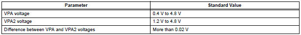
Standard voltage
2 CHECK HARNESS AND CONNECTOR (ACCELERATOR PEDAL POSITION SENSOR - ECM)
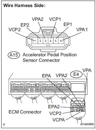
- Disconnect the A15 Accelerator Pedal Position (APP) sensor connector.
- Disconnect the E4 ECM connector.
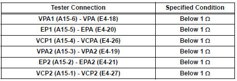
- Measure the resistance according to the value(s) in the table below.
Standard resistance : Check for open
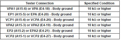
Check for short
- Reconnect the APP sensor connector.
- Reconnect the ECM connector.
3 INSPECT ECM (VCPA AND VCP2 VOLTAGE)
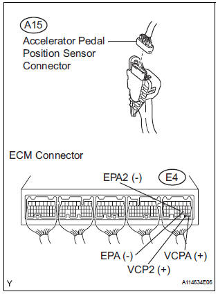
- Disconnect the A15 APP sensor connector.
- Turn the ignition switch to the ON position.
- Measure the voltage according to the value(s) in the table below.
Standard voltage
- Reconnect the APP sensor connector.
4 REPLACE ACCELERATOR PEDAL ROD
- Replace the accelerator pedal rod assembly
5 CHECK WHETHER DTC OUTPUT RECURS (ACCELERATOR PEDAL POSITION SENSOR DTCS)
- Connect the intelligent tester to the DLC3.
- Turn the ignition switch to the ON position and turn the tester on.
- Clear the DTCs.
- Start the engine.
- Allow the engine to idle for 15 seconds.
- Select the following menu items on the tester: DIAGNOSIS / ENHANCED OBD II / DTC INFO / CURRENT CODES.
- Read the DTCs.
Result

REPLACE ECM
 Throttle Actuator Control Throttle Body Range /
Performance
Throttle Actuator Control Throttle Body Range /
Performance
DTC P2119 Throttle Actuator Control Throttle Body Range /
Performance
DESCRIPTION
The Electronic Throttle Control System (ETCS) is composed of the throttle
actuator, Throttle Position (TP)
senso ...
 Throttle / Pedal Position Sensor / Switch "D"
Circuit Range / Performance
Throttle / Pedal Position Sensor / Switch "D"
Circuit Range / Performance
DTC P2121 Throttle / Pedal Position Sensor / Switch "D"
Circuit Range / Performance
HINT:
This DTC relates to the Accelerator Pedal Position (APP) sensor.
DESCRIPTION
Refer to DTC P2120 ...
Other materials:
TC and CG Terminal Circuit
DESCRIPTION
DTC output mode is set by connecting terminals TC and CG of the DLC3.
The DTCs are displayed by the blinking pattern of the ABS warning light.
WIRING DIAGRAM
HINT:
When warning lights continue to blink, a ground short in the wiring of terminal
TC of the DLC3 or an
internal ...
How to proceed with
troubleshooting
The intelligent tester can be used in steps 4, 6, 8 and 9.
1 VEHICLE BROUGHT TO WORKSHOP
2 CUSTOMER PROBLEM ANALYSIS
3 PASSENGER AIRBAG ON/OFF INDICATOR CHECK
4 DTCs CHECK (Present and Past DTCs)
Check for DTCs.
Result
5 DTCs CHART
6 CIRCUIT INSPECTION
7 REPAIR
8 CLEAR DTCs (Present ...
Short to GND in Driver Side Squib Circuit
DTC B0102/11 Short to GND in Driver Side Squib Circuit
DESCRIPTION
The driver side squib circuit consists of the center airbag sensor assembly,
the spiral cable and the
steering pad.
The circuit instructs the SRS to deploy when deployment conditions are met.
DTC B0102/11 is recorded when ...
