Toyota Sienna Service Manual: Removal
1. REMOVE ENGINE ASSEMBLY WITH TRANSAXLE
HINT: (See page EM-26)
2. REMOVE FRONT DRIVE SHAFT ASSEMBLY LH
HINT: (See page DS-6)
3. REMOVE FRONT DRIVE SHAFT ASSEMBLY RH
HINT: (See page DS-6)
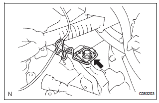
4. REMOVE TRANSMISSION CONTROL CABLE CLAMP
(a) Remove the bolt and the transmission control cable clamp.
5. REMOVE WIRE HARNESS CLAMP
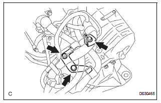
(a) Disconnect the wire harnesses from the clamp.
(b) Remove the 3 bolts and 2 clamps.
6. DISCONNECT WIRE HARNESS
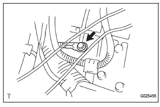
(a) Remove the bolt and disconnect the wire harness.
7. REMOVE STARTER ASSEMBLY
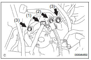
(a) Disconnect the connector (1).
(b) Remove the nut (2) and disconnect the starter wire.
(c) Remove the 2 bolts (3) and starter assembly.
8. DISCONNECT CONNECTORS
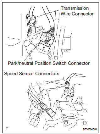
(a) Disconnect the transmission wire connector.
(b) Disconnect the park/neutral position switch connector.
(c) Disconnect the 2 speed sensor connectors.
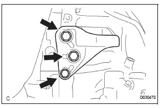
9. REMOVE TRANSMISSION CONTROL CABLE BRACKET NO.1
(a) Remove the bolt and automatic transmission oil cooler tube clamp.
(b) Remove the 2 bolts and transmission control cable bracket No.1.
10. REMOVE TRANSMISSION OIL FILLER TUBE SUBASSEMBLY
(a) Remove the ATF level gauge.
(b) Disconnect the wire harnesses 2 clamps from the oil filler tube.
(c) Remove the 2 bolts and oil filler tube.
(d) Remove the O-ring from the oil filler tube.
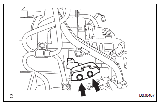
11. REMOVE OIL COOLER INLET TUBE NO.1
(a) Using SST and a wrench, disconnect the oil cooler inlet tube No.1.
SST 09023-12701
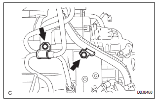
12. REMOVE OIL COOLER OUTLET TUBE NO.1
(a) Using SST and a wrench, disconnect the oil cooler outlet tube No.1.
SST 09023-12701
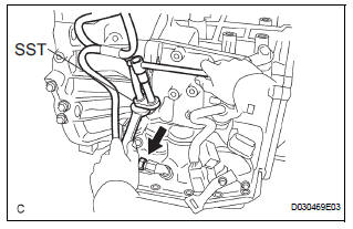
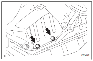
13. REMOVE ENGINE MOUNTING BRACKET FRONT
(a) Remove the 3 bolts and engine mounting bracket front.
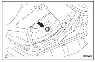
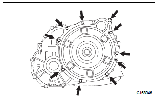
14. REMOVE AUTOMATIC TRANSAXLE ASSEMBLY
(a) Remove the 2 bolts and flywheel housing under cover.
(b) Turn the crankshaft to gain access and remove the 6 bolts while holding the crankshaft pulley bolt with a wrench.
HINT: There will be one green colored bolt.
(c) Remove the 10 bolts.
(d) Separate and remove the automatic transaxle.
15. REMOVE TORQUE CONVERTER CLUTCH ASSEMBLY
16. INSPECT TORQUE CONVERTER CLUTCH ASSEMBLY
HINT: (See page AX-170)
 Automatic transaxle assembly
Components
...
 Installation
1. Install torque converter clutch assembly
(a) Install the torque converter clutch to the automatic
transaxle.
(b) Using vernier calipers and a straight edge, measure
the dimension "A& ...
Other materials:
Linked mirror function when reversing (if equipped)
When the mirror select switch is in the L or R position, the outside rear
view mirrors will automatically angle downwards when the vehicle is
reversing in order to give a better view of the ground.
To disable this function, move the mirror select switch to the neutral
position (between L and R ...
DTC check / clear
HINT:
Illustrations may differ from the actual vehicle depending
on the device settings and options. Therefore, some
detailed areas may not be shown exactly the same as on
the actual vehicle.
If the system cannot enter the diagnostic mode, inspect all AVC-LAN
communication ...
Manual shifting test
1. Perform manual shifting test
Hint:
With this test, it can be determined whether the
trouble occurs in the electrical circuit or is a
mechanical problem in the transaxle.
If any abnormalities are found in the following test, the
problem is in the transaxle itself.
(A) disconnec ...
