Toyota Sienna Service Manual: Engine Coolant Temperature Circuit
DTC P0115 Engine Coolant Temperature Circuit
DTC P0117 Engine Coolant Temperature Circuit Low Input
DTC P0118 Engine Coolant Temperature Circuit High Input
DESCRIPTION
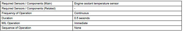
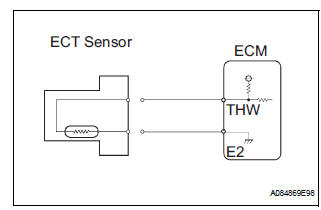
A thermistor is built into the Engine Coolant Temperature (ECT) sensor, of which the resistance value varies according to the ECT.
The structure of the sensor and its connection to the ECM are the same as those of the Intake Air Temperature (IAT) sensor.
HINT: When any of DTCs P0115, P0117 and P0118 are set, the ECM enters fail-safe mode. During fail-safe mode, the ECT is estimated to be 80C (176F) by the ECM. Fail-safe mode continues until a pass condition is detected.
|
DTC No. |
Proceed to |
DTC Detection Condition |
Trouble Area |
| P0115 | Step 1 | Open or short in Engine Coolant Temperature (ECT) sensor circuit for 0.5 seconds (1 trip detection logic) |
|
| P0117 | Step 4 | Short in Engine Coolant Temperature (ECT) sensor circuit for 0.5 seconds (1 trip detection logic) |
|
| P0118 | Step 2 | Open in Engine Coolant Temperature (ECT) sensor circuit for 0.5 seconds (1 trip detection logic) |
|
HINT: When any of these DTCs are set, check the ECT by selecting the following menu items on the intelligent tester: DIAGNOSIS / ENHANCED OBD II / DATA LIST / PRIMARY / COOLANT TEMP.

MONITOR DESCRIPTION
The Engine Coolant Temperature (ECT) sensor is used to monitor the ECT. The ECT sensor has a thermistor with a resistance that varies according to the temperature of the engine coolant. When the coolant temperature becomes low, the resistance in the thermistor increases. When the temperature becomes high, the resistance drops.
These variations in resistance are reflected in the voltage output from the sensor. The ECM monitors the sensor voltage and uses this value to calculate the ECT. When the sensor output voltage deviates from the normal operating range, the ECM interprets this as a fault in the ECT sensor and sets a DTC.
Example: If the sensor voltage output is -40C (-40F) for 0.5 seconds or more, the ECM determines that there is an open in the ECT sensor circuit, and sets DTC P0118. Conversely, if the voltage output is more than 140C (284F) for 0.5 seconds or more, the ECM determines that there is a short in the sensor circuit, and sets DTC P0117.
If the malfunction is not repaired successfully, a DTC is set 0.5 seconds after the engine is next started.
MONITOR STRATEGY

TYPICAL ENABLING CONDITIONS

TYPICAL MALFUNCTION THRESHOLDS
P0115:

P0117:

P0118

COMPONENT OPERATING RANGE

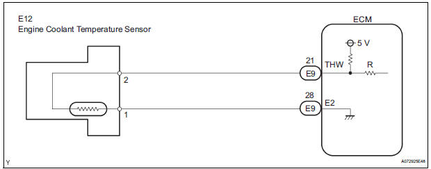
WIRING DIAGRAM
INSPECTION PROCEDURE
HINT:
- If other DTCs relating to different systems that have terminal E2 as the ground terminal are output simultaneously, terminal E2 may have an open circuit.
- Read freeze frame data using the intelligent tester. The ECM records vehicle and driving condition information as freeze frame data the moment a DTC is stored. When troubleshooting, freeze frame data can be helpful in determining whether the vehicle was running or stopped, whether the engine was warmed up or not, whether the air-fuel ratio was lean or rich, as well as other data recorded at the time of a malfunction.
1 READ VALUE OF INTELLIGENT TESTER (ENGINE COOLANT TEMPERATURE)
- Connect the intelligent tester to the DLC3.
- Turn the ignition switch to the ON position.
- Turn the tester on.
- Select the following menu items: DIAGNOSIS / ENHANCED OBD II / DATA LIST / PRIMARY / COOLANT TEMP.
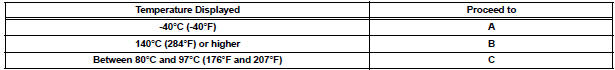
- Read the value displayed on the tester.
Standard: Between 80C and 97C (176F and 207F) with warm engine.
HINT:
- If there is an open circuit, the intelligent tester indicates -40C (-40F).
- If there is a short circuit, the intelligent tester indicates 140C (284F) or higher.
2 READ VALUE OF INTELLIGENT TESTER (CHECK FOR OPEN IN WIRE HARNESS)
- Disconnect the E12 Engine Coolant Temperature (ECT) sensor connector.
- Connect terminals 1 and 2 of the ECT sensor connector on the wire harness side.
- Connect the intelligent tester to the DLC3.
- Turn the ignition switch to the ON position.
- Turn the tester on.
- Select the following menu items: DIAGNOSIS / ENHANCED OBD II / DATA LIST / PRIMARY / COOLANT TEMP.
- Read the value displayed on the tester.
Standard: 140C (284F) or higher
- Reconnect the ECT sensor connector.
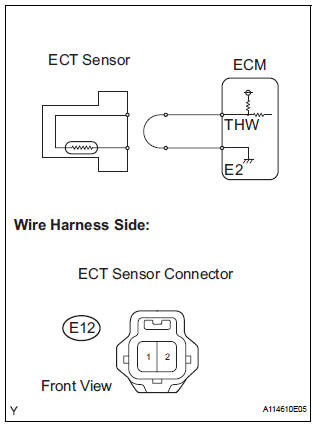
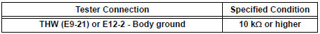
3 CHECK HARNESS AND CONNECTOR (ENGINE COOLANT TEMPERATURE SENSOR - ECM)
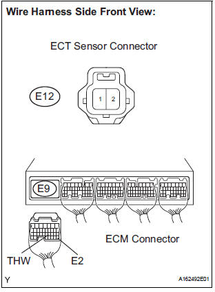
- Disconnect the E12 ECT sensor connector.
- Disconnect the E9 ECM connector.
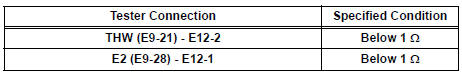
- Measure the resistance according to the value(s) in the table below.
Standard resistance
- Reconnect the ECM connector.
- Reconnect the ECT connector.
REPLACE ECM
4 READ VALUE OF INTELLIGENT TESTER (CHECK FOR SHORT IN WIRE HARNESS)
- Disconnect the E12 ECT sensor connector.
- Connect the intelligent tester to the DLC3.
- Turn the ignition switch to the ON position.
- Turn the tester on.
- Select the following menu items: DIAGNOSIS / ENHANCED OBD II / DATA LIST / PRIMARY / COOLANT TEMP.
- Read the value displayed on the tester.
Standard: -40C (-40F)
- Reconnect the ECT sensor connector
5 CHECK HARNESS AND CONNECTOR (ENGINE COOLANT TEMPERATURE SENSOR - ECM)
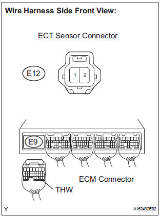
- Disconnect the E12 ECT sensor connector.
- Disconnect the E9 ECM connector.
- Measure the resistance according to the value(s) in the table below.
Standard resistance
- Reconnect the ECT sensor connector.
- Reconnect the ECM connector.
REPLACE ECM
 Intake Air Temperature Sensor Gradient Too
High
Intake Air Temperature Sensor Gradient Too
High
DTC P0111 Intake Air Temperature Sensor Gradient Too
High
DESCRIPTION
The Intake Air Temperature (IAT) sensor, mounted on the Mass Air Flow (MAF)
meter, monitors the IAT.
The IAT sensor ha ...
 Engine Coolant Temperature Circuit Range /
Performance Problem
Engine Coolant Temperature Circuit Range /
Performance Problem
DTC P0116 Engine Coolant Temperature Circuit Range /
Performance Problem
DESCRIPTION
Refer to DTC P0115
DTC No.
DTC Detection Condition
Trouble Area
P0116
...
Other materials:
Disassembly
1. REMOVE FRONT BUMPER ENERGY ABSORBER
2. REMOVE FRONT BUMPER REINFORCEMENT SUBASSEMBLY
Remove the 6 bolts and the front bumper
reinforcement sub-assembly.
3. REMOVE FRONT BUMPER SIDE SUPPORT LH
Remove the screw.
Disengage the 2 clips and remove the front bumper
side suppor ...
Adjustment
HINT:
On the RH side, use the same procedures as on the LH
side.
Since a centering bolt is used as door hinge mounting
bolts on the body side and the door side, the door cannot
be adjusted with them on. Substitute a bolt with a washer
for the centering bolt.
1. INSPECT BACK DOOR PAN ...
Operation check
1. CHECK WINDOW LOCK SWITCH
Check that the passenger side power window and
slide door power window operation is disabled when
the window lock switch of the power window master
switch is pressed.
Check that the passenger side power window and
slide door power windows can ...
