Toyota Sienna Service Manual: Scratched / Reversed Disc
DTC 62-46 Scratched / Reversed Disc
DTC 63-46 Scratched / Reversed Disc
DESCRIPTION
|
DTC No. |
DTC Detecting Condition |
Trouble Area |
|
62-46 |
Scratches or dirt is found on CD surface or CD is set upside down. |
|
|
63-46 |
Scratches or dirt is found on CD surface or CD is set upside down. |
INSPECTION PROCEDURE
HINT: After the inspection is completed, clear the DTCs.
1 CHECK THAT CD IS INSERTED PROPERLY
- Check whether or not the CD is inserted upside down.
OK: CD is properly inserted.
2 CHECK DISC
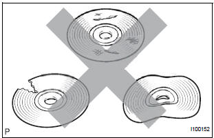
- Check that the disc is not deformed or cracked.
OK: No deformation or cracks on the disc.
3 DISC CLEANING
- Disc cleaning
- If dirt is on the disc surface, wipe it clean with a soft cloth from the inside to the outside in a radial direction.
NOTICE: Do not use a conventional record cleaner or anti-static preservative
4 CLEAR DTC
- Clear the DTCs
5 RECHECK DTC
- Recheck for DTCs and check if the same trouble occurs again.
OK: Malfunction disappears.
6 REPLACE DISC WITH ANOTHER AND RECHECK
- Replace the disc with another and recheck.
- Replace the disc with another normal one.
- Clear the DTCs.
- Recheck for DTCs and check if the same trouble occurs again.
OK: Malfunction disappears
END
 Eject Error/ Elevator Error/ Clamp Error/ Eject Error/ Elevator Error/ Clamp
Error
Eject Error/ Elevator Error/ Clamp Error/ Eject Error/ Elevator Error/ Clamp
Error
DTC 62-45 Eject Error
DTC 62-51 Elevator Error
DTC 62-52 Clamp Error
DTC 63-45 Eject Error
DTC 63-51 Elevator Error
DTC 63-52 Clamp Error
DESCRIPTION
DTC No.
DTC Detecting Con ...
 High Temperature
DTC 62-47 High Temperature
DTC 63-47 High Temperature
DESCRIPTION
DTC No.
DTC Detecting Condition
Trouble Area
62-47
Sensor detects that CD unit temperature ...
Other materials:
How to proceed with troubleshooting
The intelligent tester can be used at steps 3, 7, 10, and 13.
1 VEHICLE BROUGHT TO WORKSHOP
2 CUSTOMER PROBLEM ANALYSIS
(a) Interview the customer to confirm the trouble.
3 DTC CHECK/CLEAR AND FREEZE FRAME DATA
4 PROBLEM SYMPTOM CONFIRMATION
5 PROBLEM SYMPTOM SIMULATION
6 SYMPTOM SI ...
Cleaning and protecting
the vehicle exterior
Perform the following to protect the vehicle and maintain it in
prime condition:
Working from top to bottom, liberally apply water to the vehicle
body, wheel wells and underside of the vehicle to remove any dirt
and dust.
Wash the vehicle body using a sponge or soft cloth, such as a
cha ...
Short to B+ in Front Passenger Side Squib Circuit
DTC B0108/52 Short to B+ in Front Passenger Side Squib Circuit
DESCRIPTION
The front passenger side squib circuit consists of the center airbag sensor
assembly and the front
passenger airbag assembly.
The circuit instructs the SRS to deploy when deployment conditions are met.
DTC B0108/52 ...
