Toyota Sienna Service Manual: Short in Side Squib LH Circuit
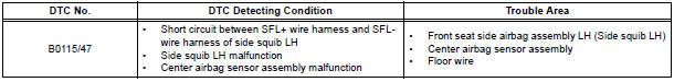
DTC B0115/47 Short in Side Squib LH Circuit
DESCRIPTION
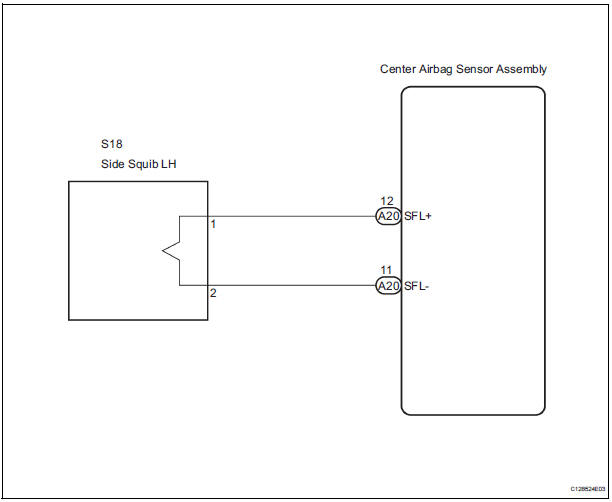
The side squib LH circuit consists of the center airbag sensor assembly and the front seat side airbag assembly LH.
This circuit instructs the SRS to deploy when deployment conditions are met.
DTC B0115/47 is recorded when a short circuit is detected in the side squib LH circuit.
WIRING DIAGRAM
INSPECTION PROCEDURE
HINT:
- Perform the simulation method by selecting the "check mode" (signal check) with the intelligent tester
- After selecting the "check mode" (signal check), perform the simulation method by wiggling each connector of the airbag system or driving the vehicle on a city or rough road
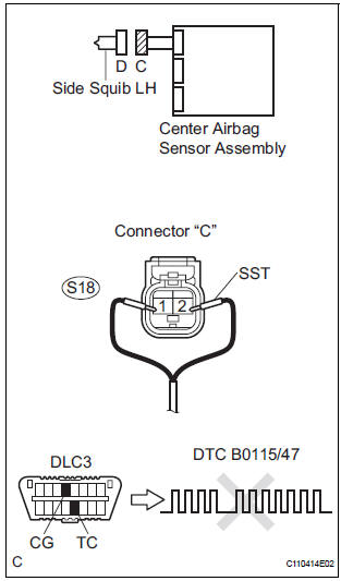
1 CHECK FRONT SEAT SIDE AIRBAG ASSEMBLY LH (SIDE SQUIB LH)
- Turn the ignition switch to the LOCK position.
- Disconnect the negative (-) terminal cable from the battery, and wait for at least 90 seconds.
- Disconnect the connectors from the front seat side airbag assembly LH.
- Connect the black wire side of SST (resistance 2.1 Ω) to the floor wire.
CAUTION: Never connect a tester to the front seat side airbag assembly LH (side squib LH) for measurement, as this may lead to a serious injury due to airbag deployment.
NOTICE: Do not forcibly insert the SST into the terminals of the connector when connecting.
Insert the SST straight into the terminals of the connector.
SST 09843-18060
- Connect the negative (-) terminal cable to the battery, and wait for at least 2 seconds.
- Turn the ignition switch to the ON position, and wait for at least 60 seconds.
- Clear the DTCs stored in memory.
- Turn the ignition switch to the LOCK position.
- Turn the ignition switch to the ON position, and wait for at least 60 seconds.
- Check the DTCs.
OK: DTC B0115/47 is not output.
HINT: Codes other than DTC B0115/47 may be output at this time, but they are not related to this check.
REPLACE FRONT SEAT ASSEMBLY LH
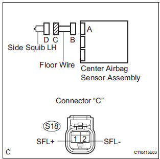
2 CHECK FLOOR WIRE (SIDE SQUIB LH CIRCUIT)
- Turn the ignition switch to the LOCK position.
- Disconnect the negative (-) terminal cable from the battery, and wait for at least 90 seconds.
- Disconnect the SST (resistance 2.1 Ω) from the floor wire.
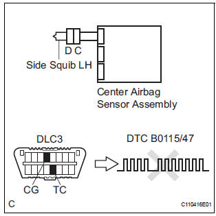
- Disconnect the connector from the center airbag sensor assembly.
- Release the activation prevention mechanism built into connector "B".
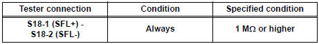
- Measure the resistance according to the value(s) in the table below.
Standard resistance
3 CHECK CENTER AIRBAG SENSOR ASSEMBLY
- Connect the connectors to the front seat side airbag assembly LH and the center airbag sensor assembly.
- Connect the negative (-) terminal cable to the battery, and wait for at least 2 seconds.
- Turn the ignition switch to the ON position, and wait for at least 60 seconds.
- Clear the DTCs stored in memory.
- Turn the ignition switch to the LOCK position.
- Turn the ignition switch to the ON position, and wait for at least 60 seconds.
- Check the DTCs.
OK: DTC B0115/47 is not output.
HINT: Codes other than code B0115/47 may be output at this time, but they are not related to this check.
USE SIMULATION METHOD TO CHECK
 USE SIMULATION METHOD TO CHECK
DTC B0113/42 Short to B+ in Side Squib RH Circuit
DESCRIPTION
The side squib RH circuit consists of the center airbag sensor assembly and
the front seat side airbag
assembly RH.
This circuit i ...
 Open in Side Squib LH Circuit
DTC B0116/48 Open in Side Squib LH Circuit
DESCRIPTION
The side squib LH circuit consists of the center airbag sensor assembly and
the front seat side assembly
LH.
This circuit instructs the S ...
Other materials:
On-vehicle inspection
1. INSPECT CAMSHAFT TIMING CONTROL VALVE ASSEMBLY
Connect the intelligent tester to the DLC3.
Turn the ignition switch to the ON position.
Start the engine and warm it up.
Select the intelligent tester from the ACTIVE TEST
menu.
Check the engine speed ...
Scratched / Reversed Disc
DTC 44-46 Scratched / Reversed Disc
DESCRIPTION
DTC No.
DTC Detecting Condition
Trouble Area
44-46
Scratches or dirt is found on DVD surface or DVD is set
upside down.
DVD
Television display assembly
INSPECTION PROCEDU ...
Disassembly
1. REMOVE REAR SEAT LEG COVER LH
Remove the 2 screws and seat leg cover.
2. REMOVE REAR SEAT LEG COVER RH
Remove the 2 screws and seat leg cover.
3. REMOVE REAR SEAT LEG SIDE COVER LH
Remove the 2 screws and leg side cover.
4. REMOVE LH SEAT REAR SEAT LOCK COVE ...
