Toyota Sienna Service Manual: Rear Air Conditioning Relay Circuit
DESCRIPTION
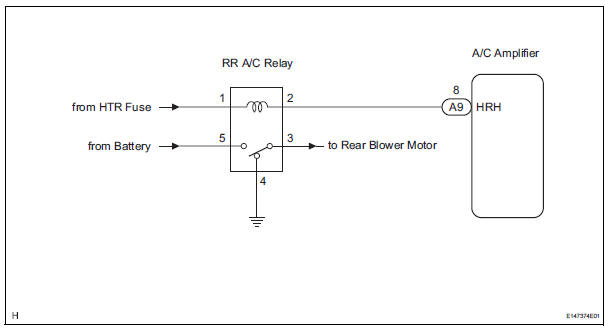
The RR A/C relay is switched on by signals from the A/C amplifier. It supplies power to the rear blower motor.
WIRING DIAGRAM
INSPECTION PROCEDURE
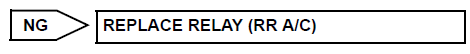
1 INSPECT RELAY (RR A/C)
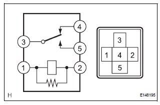
(a) Remove the RR A/C relay from the No. 3 relay block.
(b) Measure the resistance according to the value(s) in the table below.
Standard resistance 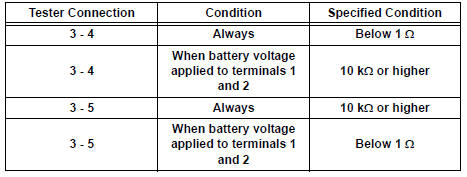

2 CHECK HARNESS AND CONNECTOR (A/C AMPLIFIER - BATTERY)
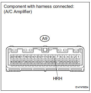
(a) Disconnect the connector from the A/C amplifier.
(b) Measure the voltage according to the value(s) in the table below.
Standard voltage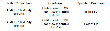

PROCEED TO NEXT CIRCUIT INSPECTION SHOWN IN PROBLEM SYMPTOMS TABLE
 Rear Air Conditioning Control Panel Circuit
DESCRIPTION
This is the rear A/C system control signal circuit as well as the power
supply circuit of the rear A/C control
assembly.
Pulse signals regarding rear A/C control panel switch operat ...
 Rear Blower Motor Circuit
DESCRIPTION
Power to the rear blower motor is supplied from the battery via the RR A/C
relay.
The rear blower motor speed level varies between 0 and 31 based on the voltage
difference measured ...
Other materials:
Starter Relay Circuit High
MONITOR DESCRIPTION
While the engine is being cranked, the positive battery voltage is applied to
terminal STA of the ECM.
If the ECM detects the Starter Control (STA) signal while the vehicle is being
driven, it determines that
there is a malfunction in the STA circuit. The ECM then il ...
Power Window cannot be Operated by Wireless Operation
DESCRIPTION
When the switch on the transmitter is operated during normal operating
conditions, the
multiplex network body ECU sends a request signal to the master switch and the
regulator switches which
then drive the applicable power window motors.
INSPECTION PROCEDURE
1 CHECK WIRELESS DOO ...
Reassembly
1. INSTALL RACK STEERING PISTON RING
(a) Coat a new O-ring with power steering fluid and
install it onto the power steering rack.
(b) Expand a new rack steering piston ring with your
fingers.
NOTICE:
Be careful not to over expand the rack steering
piston ring.
(c) Coat a new rack steer ...
