Toyota Sienna Service Manual: Solar Sensor Circuit (Passenger Side)
DTC B1421/21 Solar Sensor Circuit (Passenger Side)
DESCRIPTION
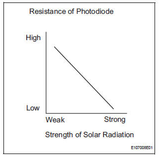
The solar sensor, which is installed on the upper side of the instrument
panel, detects sunlight and
controls the air conditioning in AUTO mode. The output voltage from the solar
sensor varies according to
the amount of sunlight. When the sunlight increases, the output voltage
increases. As the sunlight
decreases, the output voltage decreases. The A/C amplifier detects voltage
output from the solar sensor. 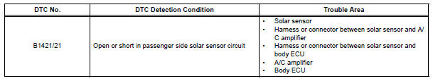
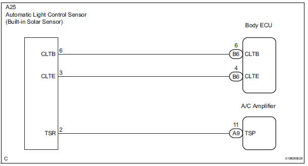
WIRING DIAGRAM
INSPECTION PROCEDURE
HINT:
- If DTC B1244 is output at the same time, troubleshoot DTC B1244 first (See page LI-16).
- If the check is performed in a dark place, DTC B1421/21 or B1424/24 (solar sensor circuit abnormal) may be output even though the system is normal.
1 READ VALUE OF INTELLIGENT TESTER
(a) Connect the intelligent tester to the DLC3.
(b) Turn the ignition switch to the ON position and turn the intelligent tester main switch on.
(c) Expose the sensing portion of the solar sensor to light.
HINT: Use an incandescent light for inspection.
(d) Select the item below in the DATA LIST, and read the display on the intelligent tester.
DATA LIST / AIR CONDITIONER: 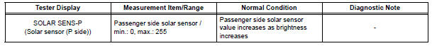
OK: The display is as specified in the normal condition column.
Result 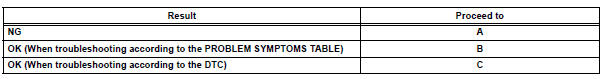
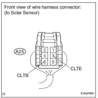
2 CHECK HARNESS AND CONNECTOR (SOLAR SENSOR)
(a) Disconnect the solar sensor connector.
(b) Measure the voltage according to the value(s) in the table below.
Standard voltage 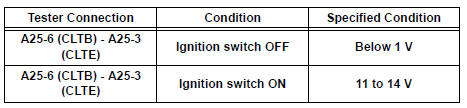

3 CHECK HARNESS AND CONNECTOR (SOLAR SENSOR - BODY ECU)
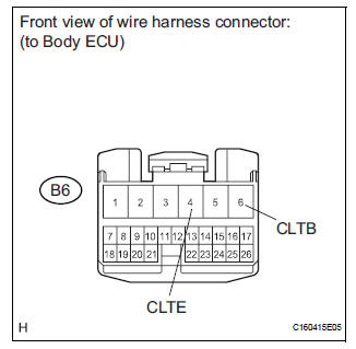
(a) Disconnect the body ECU connector.
(b) Measure the resistance according to the value(s) in the table below.
Standard resistance 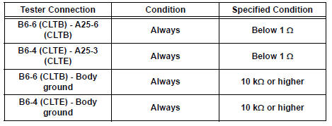

REPLACE BODY ECU
4 CHECK SOLAR SENSOR
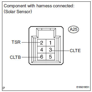
(a) Remove the solar sensor with its connector still connected.
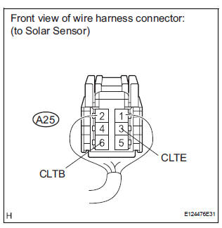
(b) Connect the positive (+) lead from the battery to terminal 6 (CLTB), and the negative (-) lead to terminal 3 (CLTE) of the solar sensor.
(c) Measure the voltage according to the value(s) in the table below.
Standard voltage 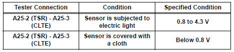
NOTICE: While using the battery during inspection, do not bring the positive and negative tester probes too close to each other as a short circuit may occur.
HINT:
- Use an incandescent light for inspection. Bring it within about 30 cm (11.8 in.) of the solar sensor.
- As the inspection light is moved away from the sensor, the voltage increases.

5 CHECK HARNESS AND CONNECTOR (SOLAR SENSOR - A/C AMPLIFIER)

(a) Disconnect the solar sensor connector.

(b) Disconnect the A/C amplifier connector.
(c) Measure the resistance according to the value(s) in the table below.
Standard resistance 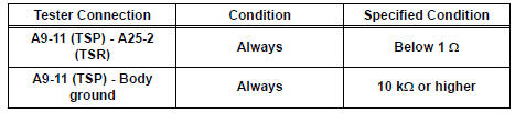

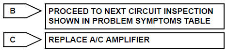
REPLACE A/C AMPLIFIER
 Rear Room Temperature Sensor Circuit
DESCRIPTION
This sensor detects the rear cabin temperature that is used as the basis for
temperature control and
sends a signal to the A/C amplifier.
WIRING DIAGRAM
INSPECTION PROCEDURE
1 R ...
 Compressor Lock Sensor Circuit
DTC B1422/22 Compressor Lock Sensor Circuit
SYSTEM DESCRIPTION
The ECM sends an engine speed signal to the A/C amplifier via CAN
communication and BEAN
communication.
The A/C amplifier reads t ...
Other materials:
Auxiliary boxes
Type A
Push the lid.
Type B
Push down the knob.
Type C (if equipped)
Type D
Type E (if equipped)
Type F
Lift the lid.
Type G (if equipped)
Removing the second center seat.
Type H (if equipped)
Type I (if equip ...
Communication Error of Yaw Rate Sensor
DTC U0123 Communication Error of Yaw Rate Sensor
DESCRIPTION
This circuit detects the yaw rate of the vehicle and transmits its signal to
the skid control ECU and
distance control ECU.
DTC No.
DTC Detection Condition
Trouble Area
U0123
While the dynamic ...
Open in Driver Side Squib 2nd Step Circuit
DTC B1181/18 Open in Driver Side Squib 2nd Step Circuit
DESCRIPTION
The driver side squib 2nd step circuit consists of the center airbag sensor
assembly, the spiral cable and
the steering pad.
The circuit instructs the SRS to deploy when deployment conditions are met.
DTC B1181/18 is reco ...
