Toyota Sienna Service Manual: Rear Room Temperature Sensor Circuit
DESCRIPTION
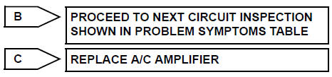
This sensor detects the rear cabin temperature that is used as the basis for
temperature control and
sends a signal to the A/C amplifier.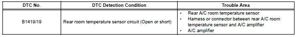
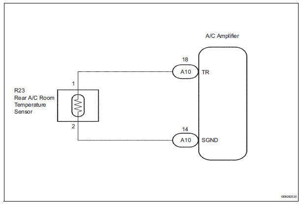
WIRING DIAGRAM
INSPECTION PROCEDURE
1 READ VALUE OF INTELLIGENT TESTER
(a) Connect the intelligent tester to the DLC3.
(b) Turn the ignition switch to the ON position and turn the intelligent tester main switch on.
(c) Select the item below in the DATA LIST, and read the display on the intelligent tester.
DATA LIST / AIR CONDITIONER: 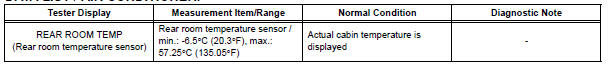
OK: The display is as specified in the normal condition column.
Result 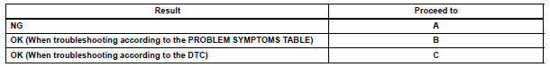

2 INSPECT REAR A/C ROOM TEMPERATURE SENSOR
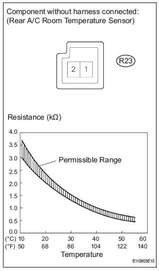
(a) Remove the rear A/C room temperature sensor.
(b) Measure the resistance according to the value(s) in the table below.
Standard resistance 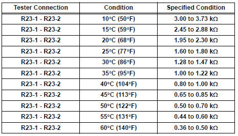
NOTICE:
- Hold the sensor only by its connector. Touching the sensor may change the resistance value.
- When measuring, the sensor temperature must be the same as the rear cabin temperature.
HINT: As the temperature increases, the resistance decreases (see the graph).

3 CHECK HARNESS AND CONNECTOR (REAR A/C ROOM TEMPERATURE SENSOR - A/C AMPLIFIER)
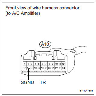
(a) Disconnect the connector from the A/C amplifier.
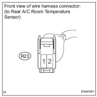
(b) Disconnect the connector from the rear A/C room temperature sensor.
(c) Measure the resistance according to the value(s) in the table below.
Standard resistance 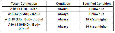

REPLACE A/C AMPLIFIER
 Rear evaporator temperature sensor circuit
DESCRIPTION
The rear evaporator temperature sensor is installed on the rear evaporator.
It detects the rear evaporator
temperature. The sensor sends a signal to the A/C amplifier. The resistance o ...
 Solar Sensor Circuit (Passenger Side)
DTC B1421/21 Solar Sensor Circuit (Passenger Side)
DESCRIPTION
The solar sensor, which is installed on the upper side of the instrument
panel, detects sunlight and
controls the air conditioni ...
Other materials:
Removal
1. DISCONNECT CABLE FROM NEGATIVE BATTERY
TERMINAL
2. REMOVE ROOF HEADLINING ASSEMBLY
HINT:
Refer to the instructions for REMOVAL of the ROOF
HEADLINING (See page IR-6).
3. REMOVE TIRE PRESSURE WARNING RECEIVER ASSEMBLY
(a) Remove the bolt.
(b) Disconnect the connector and remove the ...
Monitor result information
If you use a generic scan tool, multiply the test value by
the scaling value listed below.
...
DTC check / clear
1. DTC CHECK
HINT:
When DTC B1150/23 is detected as a result of
troubleshooting for "Airbag System", perform
troubleshooting for the Occupant Classification System.
Check the DTCs.
Connect the intelligent tester to the DLC3
Turn the ignition switch to ...
