Toyota Sienna Service Manual: Television Display Power Source Circuit
DESCRIPTION
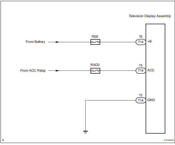
This is the power source circuit to operate the television display assembly.
WIRING DIAGRAM
INSPECTION PROCEDURE
1 INSPECT TELEVISION DISPLAY ASSEMBLY
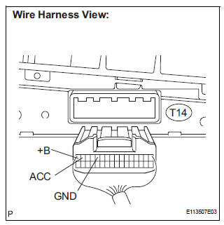
- Disconnect the connector from the television display assembly.
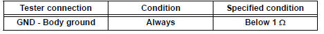
- Measure the resistance according to the value(s) in the table below.
Standard resistance
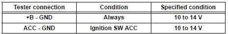
- Measure the voltage according to the value(s) in the table below.
Standard voltage
PROCEED TO NEXT CIRCUIT INSPECTION SHOWN IN PROBLEM SYMPTOMS TABLE
 Radio and Navigation Assembly Power Source Circuit
DESCRIPTION
This is the power source circuit to operate the radio and navigation
assembly.
WIRING DIAGRAM
INSPECTION PROCEDURE
1 INSPECT RADIO AND NAVIGATION ASSEMBLY
Disconnect the ...
 Navigation receiver
COMPONENTS
...
Other materials:
Steering Angle Sensor Zero Point Malfunction
DTC C1290/66 Steering Angle Sensor Zero Point Malfunction
DESCRIPTION
The skid control ECU acquires steering angle sensor zero point every time the
ignition switch is turned to
the ON position and the vehicle is driven at 35 km/h (22 mph) or more for
approximately 5 seconds. The
ECU also sto ...
Ambient temperature sensor circuit
DTC B1412/12 Ambient Temperature Sensor Circuit
DESCRIPTION
The ambient temperature sensor is installed in front of the condenser to
detect the ambient temperature
which is used to control the air conditioner "AUTO" mode. This sensor is
connected to the A/C amplifier
and detects fl ...
TC and CG Terminal Circuit
DESCRIPTION
DTC output mode is set by connecting terminals 13 (TC) and 4 (CG) of the
DLC3. The DTCs are indicated
by blinks of the tire pressure warning light.
WIRING DIAGRAM
HINT:
When each warning light blinks continuously, a ground short in the wiring of
terminal TC of the DLC3 or an ...
