Toyota Sienna Service Manual: Wrong Disc/ Disc cannot be Read
DTC 63-41 Wrong Disc
DTC 63-42 Disc cannot be Read
DESCRIPTION
|
DTC No. |
DTC Detection Condition |
Trouble Area |
| 63-41 | An unsuitable disc is inserted |
|
| 63-42 | The disc cannot be read |
INSPECTION PROCEDURE
HINT: After the inspection is completed, clear the DTCs.
1 CHECK DISC
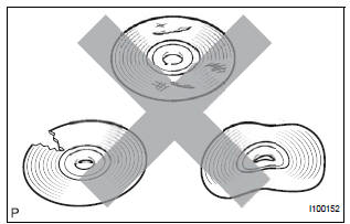
- Check that the disc is not deformed or cracked.
OK: No deformations or cracks on the disc.
2 DISC CLEANING
- Disc cleaning
- If dirt is on the disc surface, wipe it clean with a soft cloth from the inside to outside in a radial direction.
NOTICE: Do not use a conventional record cleaner or anti-static preservative
3 CLEAR DTC
- Clear the DTCs
4 RECHECK DTC
- Recheck for DTCs and check if the same trouble occurs again.
OK: Malfunction disappears
5 REPLACE DISC WITH ANOTHER AND RECHECK
- Replace the disc with another and recheck.
- Replace the disc with another normal one.
- Clear the DTCs.
- Recheck for DTCs and check if the same trouble occurs again.
OK: Malfunction disappears.
END
 CD Changer Mechanical Error/ CD Insertion and Ejection Error/ CD Reading
Abnormal
CD Changer Mechanical Error/ CD Insertion and Ejection Error/ CD Reading
Abnormal
DTC 63-10 CD Changer Mechanical Error
DTC 63-11 CD Insertion and Ejection Error
DTC 63-12 CD Reading Abnormal
DESCRIPTION
DTC No.
DTC Detection Condition
Trouble Area
...
 CD-ROM Abnormal
DTC 63-43 CD-ROM Abnormal
DESCRIPTION
DTC No.
DTC Detection Condition
Trouble Area
63-43
CD-ROM operation is abnormal
CD
Radio and navigation ...
Other materials:
Glossary of sae and Toyota terms
This glossary lists all SAE-J1930 terms and abbreviations
used in this manual in compliance with SAE
recommendations, as well as their TOYOTA equivalents.
...
Illumination Circuit
DESCRIPTION
Power is supplied to the radio and navigation assembly and steering pad
switch illumination when the
light control switch is in the TAIL or HEAD position.
WIRING DIAGRAM
INSPECTION PROCEDURE
NOTICE:
The vehicle is equipped with an SRS (Supplemental Restraint System) such as t ...
Removal
HINT:
Replace the RH side by the same procedures as the LH side.
1. REMOVE REAR WHEEL
2. REMOVE REAR DISC BRAKE CALIPER ASSEMBLY
LH
(a) Removing the 2 bolts, separate the rear disc brake
caliper assembly LH for disc rear brake type.
NOTICE:
Using a string and so on, hang down the disc
brake ...
