Toyota Sienna Service Manual: Illumination Circuit
DESCRIPTION
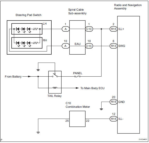
Power is supplied to the radio and navigation assembly and steering pad switch illumination when the light control switch is in the TAIL or HEAD position.
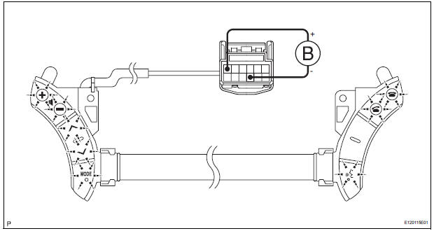
WIRING DIAGRAM
INSPECTION PROCEDURE
NOTICE: The vehicle is equipped with an SRS (Supplemental Restraint System) such as the airbags. Before servicing (including removal or installation of parts), be sure to read the precautionary notice for the Supplemental Restraint System
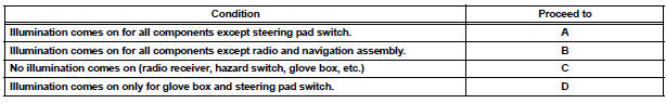
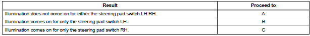
1 CHECK ILLUMINATION
- Check if the illumination for the radio and navigation assembly, steering pad switch, glove box or others (Hazard switch, cigarette lighter, etc.) comes on when the light control switch is turned to the HEAD or TAIL position.
Result
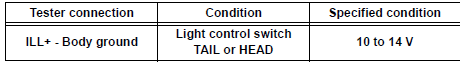
2 CHECK HARNESS AND CONNECTOR (BATTERY - SPIRAL CABLE SUB-ASSEMBLY)
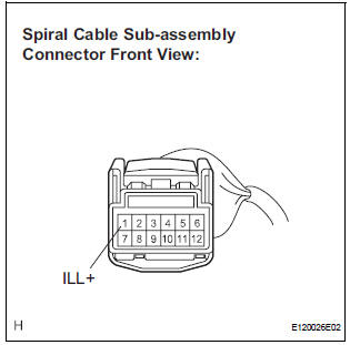
- Disconnect the spiral cable sub-assembly connector.
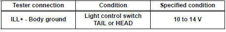
- Measure the voltage according to the value(s) in the table below.
Standard voltage
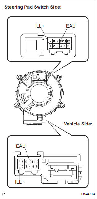
3 CHECK STEERING PAD SWITCH ASSEMBLY
- Disconnect the steering pad switch assembly connector.
- Disconnect the steering pad switch connector.
- Connect the positive (+) lead to terminal ILL+ and the negative (-) lead to terminal EAU of the steering pad switch connector.
- Check if the illumination for the steering pad switch comes on.
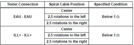
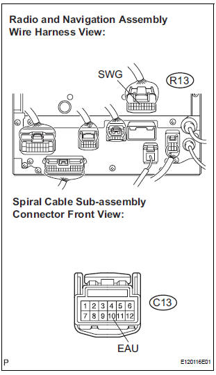
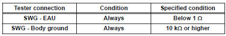
4 INSPECT SPIRAL CABLE SUB-ASSEMBLY
- Disconnect the steering pad switch and spiral cable subassembly connectors.
- Measure the resistance according to the value(s) in the table below.
Standard resistance
NOTICE: The spiral cable is an important part of the SRS airbag system. Incorrect removal or installation of the spiral cable may prevent the airbag from deploying. Be sure to read the page shown in the brackets
5 CHECK HARNESS AND CONNECTOR (SPIRAL CABLE SUB-ASSEMBLY - RADIO AND NAVIGATION ASSEMBLY)
- Disconnect the connectors from the radio and navigation assembly and spiral cable sub-assembly.
- Measure the resistance according to the value(s) in the table below.
Standard resistance
REPLACE RADIO AND NAVIGATION ASSEMBLY
6 INSPECT STEERING PAD SWITCH CABLE
- Disconnect the steering pad switch LH and the steering pad switch RH.
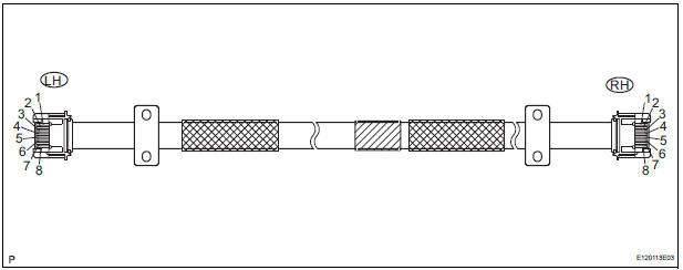
- Measure the resistance according to the value(s) in the table below
Standard resistance
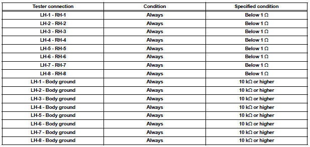
REPLACE STEERING PAD SWITCH RH
7 CHECK HARNESS AND CONNECTOR (BATTERY - RADIO AND NAVIGATION ASSEMBLY)
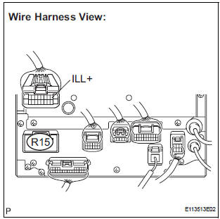
- Disconnect the radio and navigation assembly connector R15.
- Measure the voltage according to the value(s) in the table below.
Standard voltage
8 CHECK HARNESS AND CONNECTOR (RADIO AND NAVIGATION ASSEMBLY - COMBINATION METER)
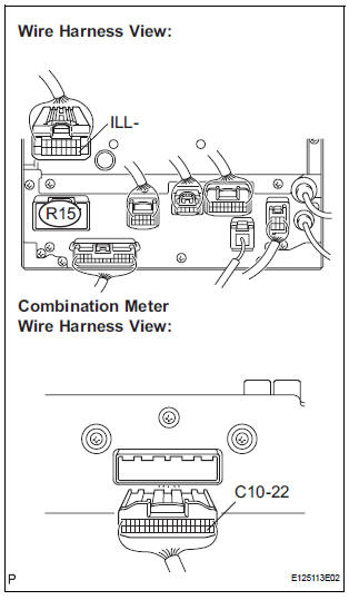
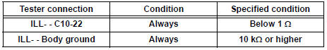
- Disconnect the radio and navigation assembly and combination meter connectors.
- Measure the resistance according to the value(s) in the table below.
Standard voltage
PROCEED TO NEXT CIRCUIT INSPECTION SHOWN IN PROBLEM SYMPTOMS TABLE
 Steering Pad Switch Circuit
DESCRIPTION
This circuit sends an operation signal from the steering pad switch to the
radio receiver.
If there is an open in the circuit, the navigation system cannot be operated
using the st ...
 Parking Brake Switch Circuit
DESCRIPTION
This circuit is from the parking brake switch to the radio and navigation
assembly.
WIRING DIAGRAM
INSPECTION PROCEDURE
1 CHECK BRAKE WARNING LIGHT
Check that the brake warni ...
Other materials:
Engine Coolant Temperature / Intake Air Temperature
Correlation
DTC P011B Engine Coolant Temperature / Intake Air Temperature
Correlation
DESCRIPTION
The ECM calculates the difference between the readings of the coolant
temperature sensor and intake air
temperature sensor. If the difference is greater than 20C (68F), the ECM will
judge this as a malfunct ...
Slip Indicator Light does not Come ON
DESCRIPTION
The skid control ECU is connected to the combination meter via CAN and
multiplex communications.
The SLIP indicator blinks during VSC and/or TRAC operation.
When the system fails, the SLIP indicator comes on to warn the driver.
WIRING DIAGRAM
Refer to Slip Indicator Light Rema ...
Park / Neutral Position Switch Circuit
DESCRIPTION
The fold seat control ECU receives signals from the Park/Neutral position
switch and controls the seat
stowing and return operations. If the shift lever is in any position other than
P the seat cannot be operated.
If the ignition switch is in ACC or IG the seat cannot be operate ...
