Toyota Sienna Service Manual: –°amshaft timing oil control valve assembly
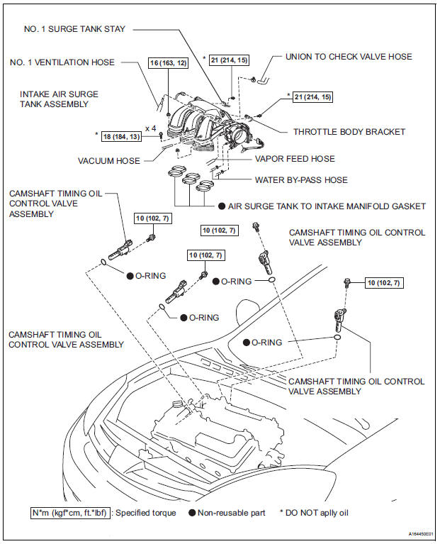
COMPONENTS
ON-VEHICLE INSPECTION
1. INSPECT CAMSHAFT TIMING CONTROL VALVE ASSEMBLY
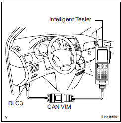
(a) Connect the intelligent tester to the DLC3.
(b) Turn the ignition switch to the ON position.
(c) Start the engine and warm it up.
(d) Select the intelligent tester from the ACTIVE TEST menu.
(e) Check the engine speed when the OCV (camshaft timing oil control valve) is operated by the intelligent tester.
OK 
REMOVAL
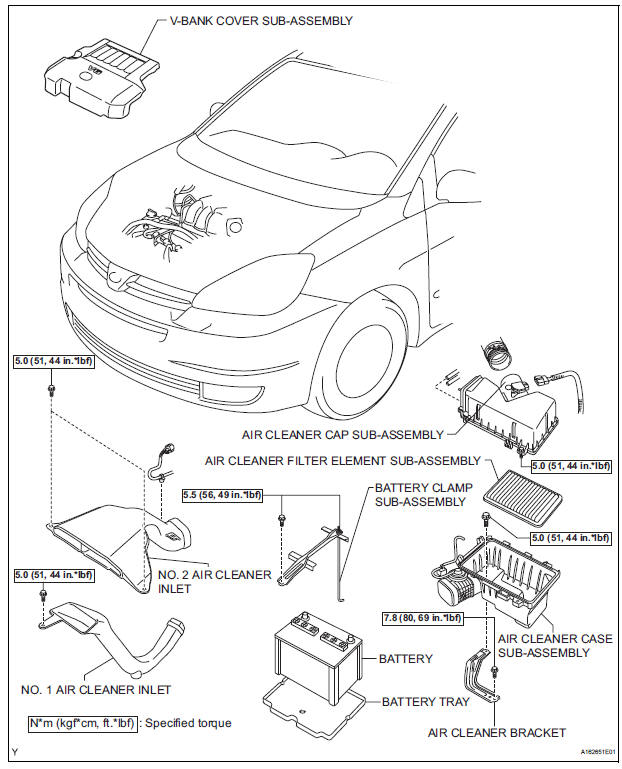
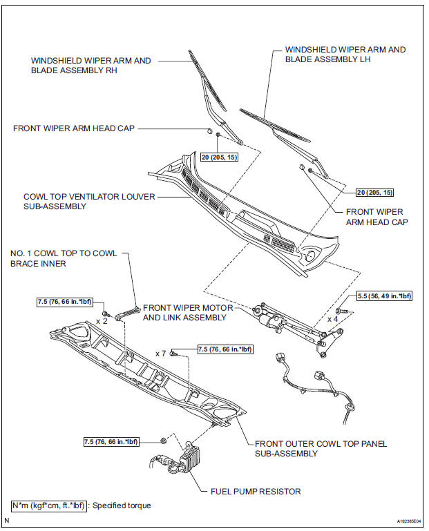
1. REMOVE WINDSHIELD WIPER MOTOR ASSEMBLY HINT: (See page WW-4) 2. REMOVE FRONT OUTER COWL TOP PANEL SUBASSEMBLY (See page EM-27) 3. DRAIN ENGINE COOLANT (See page CO-6) 4. REMOVE V-BANK COVER SUB-ASSEMBLY (See page EM-28) 5. REMOVE NO. 2 AIR CLEANER INLET (See page EM- 28) 6. REMOVE NO. 1 AIR CLEANER INLET (See page EM- 28) 7. REMOVE AIR CLEANER CAP SUB-ASSEMBLY (See page ES-493) 8. REMOVE AIR CLEANER CASE SUB-ASSEMBLY (See page EM-28) 9. REMOVE INTAKE AIR SURGE TANK ASSEMBLY (See page ES-521) 10. REMOVE CAMSHAFT TIMING OIL CONTROL VALVE ASSEMBLY (for Bank 1 Exhaust Side)
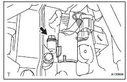
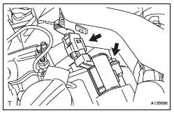
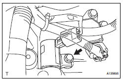
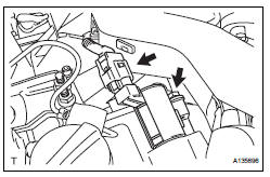
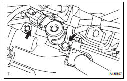
(a) Disconnect the camshaft timing oil control valve assembly connector.
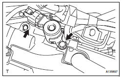
(b) Remove the bolt and camshaft timing oil control valve assembly.
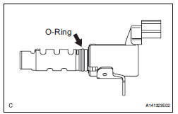
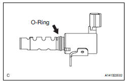
(c) Remove the O-ring from the camshaft timing oil control valve.
11. REMOVE CAMSHAFT TIMING OIL CONTROL VALVE ASSEMBLY (for Bank 1 Intake Side)
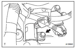
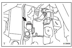
(a) Disconnect the camshaft timing oil control valve assembly connector.
(b) Remove the bolt and camshaft timing oil control valve assembly.
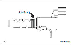
(c) Remove the O-ring from the camshaft timing oil control valve.
12. REMOVE CAMSHAFT TIMING OIL CONTROL VALVE ASSEMBLY (for Bank 2 Exhaust Side)
(a) Disconnect the camshaft timing oil control valve assembly connector.
(b) Remove the bolt and camshaft timing oil control valve assembly.
(c) Remove the O-ring from the camshaft timing oil control valve.
13. REMOVE CAMSHAFT TIMING OIL CONTROL VALVE ASSEMBLY (for Bank 2 Intake Side)
(a) Disconnect the camshaft timing oil control valve assembly connector.
(b) Remove the bolt and camshaft timing oil control valve assembly.
(c) Remove the O-ring from the camshaft timing oil control valve.
INSPECTION
1. INSPECT CAMSHAFT TIMING OIL CONTROL VALVE ASSEMBLY
(a) Resistance inspection
(1) Using an ohmmeter, measure the resistance between the terminals.
Resistance: 6.9 to 7.9 Ω at 20¬∞C (68¬∞F)
If necessary, replace the camshaft timing oil control valve assembly.
(b) Movement inspection
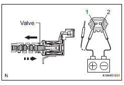
(1) Connect the positive (+) lead from the battery to terminal 1 and connect the negative (-) lead to terminal 2, and check the movement of the valve.
| NOTICE: Confirm that the valve moves freely and does not stick in any position. |
If necessary, replace the camshaft timing oil control valve assembly.
HINT: Accumulation of foreign objects causes subtle pressure leaks. The subtle pressure leaks will cause the cam to advance, and this will cause a DTC to be set.
INSTALLATION
1. INSTALL CAMSHAFT TIMING OIL CONTROL VALVE ASSEMBLY (for Bank 2 Exhaust Side)
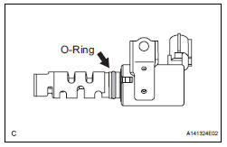
(a) Apply a light coat of engine oil to the new O-ring and install it to the camshaft timing oil control valve.
(b) Install the camshaft timing oil control valve assembly with the bolt.
Torque: 10 N*m (102 kgf*cm, 7 ft.*lbf) (c) Connect the camshaft timing oil control valve assembly connector.
2. INSTALL CAMSHAFT TIMING OIL CONTROL VALVE ASSEMBLY (for Bank 2 Intake Side)
(a) Apply a light coat of engine oil to the new O-ring and install it to the camshaft timing oil control valve.
(b) Install the camshaft timing oil control valve assembly with the bolt.
Torque: 10 N*m (102 kgf*cm, 7 ft.*lbf) Connect the camshaft timing oil control valve assembly connector.
3. INSTALL CAMSHAFT TIMING OIL CONTROL VALVE ASSEMBLY (for Bank 1 Exhaust Side)
(a) Apply a light coat of engine oil to the new O-ring and install it to the camshaft timing oil control valve.
(b) Install the camshaft timing oil control valve assembly with the bolt.
Torque: 10 N*m (102 kgf*cm, 7 ft.*lbf) (c) Connect the camshaft timing oil control valve assembly connector.
4. INSTALL CAMSHAFT TIMING OIL CONTROL VALVE ASSEMBLY (for Bank 1 Intake Side)
(a) Apply a light coat of engine oil to the new O-ring and install it to the camshaft timing oil control valve.
(b) Install the camshaft timing oil control valve assembly with the bolt.
Torque: 10 N*m (102 kgf*cm, 7 ft.*lbf) (c) Connect the camshaft timing oil control valve assembly connector.
5. INSTALL INTAKE AIR SURGE TANK ASSEMBLY (See page ES-522) 6. INSTALL AIR CLEANER CASE SUB-ASSEMBLY (See page EM-59) 7. INSTALL AIR CLEANER CAP SUB-ASSEMBLY (See page ES-496) 8. INSTALL NO. 1 AIR CLEANER INLET (See page EM- 59) 9. INSTALL NO. 2 AIR CLEANER INLET (See page EM- 60) 10. ADD ENGINE COOLANT (See page CO-7) 11. INSPECT FOR ENGINE COOLANT LEAK (See page CO-1) 12. INSPECT FOR ENGINE OIL LEAK (See page LU-6) 13. INSTALL V-BANK COVER SUB-ASSEMBLY (See page EM-63) 14. INSTALL FRONT OUTER COWL TOP PANEL SUBASSEMBLY (See page EM-61) 15. INSTALL WINDSHIELD WIPER MOTOR ASSEMBLY HINT: (See page WW-5)
 MIL Circuit
DESCRIPTION
The MIL (Malfunction Indicator Lamp) is used to indicate vehicle malfunctions
detected by the ECM.
When the ignition switch is turned to the ON position, power is supplied to the
M ...
 Throttle body
COMPONENTS
...
Other materials:
Transmitter ID1 Operation Stop
DESCRIPTION
The tire pressure warning valve and transmitters that are installed in the
tire and wheel assemblies
measure the air pressures of the tires. The measured values are transmitted to
the tire pressure warning
antenna and receiver on the body as radio waves and then sent to the ti ...
Radiator
COMPONENTS
...
Display Panel does not Open, Tilt or Tilts Improperly
INSPECTION PROCEDURE
1 CHECK RADIO AND NAVIGATION ASSEMBLY
Check for foreign matter or obstructions caught in the
moving parts of the panel.
OK:
No obstruction or foreign matter found.
2 CHECK OPERATION
Check if the navigation and audio systems function
properly.
OK:
Naviga ...
