Toyota Sienna Service Manual: Terminals of ECU
1. MULTIPLEX NETWORK GATEWAY ECU
- Disconnect the G4 ECU connector.
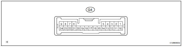
- Measure the voltage between the specified terminals on the wire harness side connector.
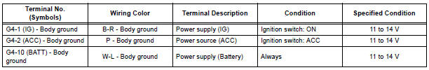
If the result is not as specified, there may be a malfunction on the wire harness side.
- Measure the resistance between the specified terminals on the wire harness side connector.
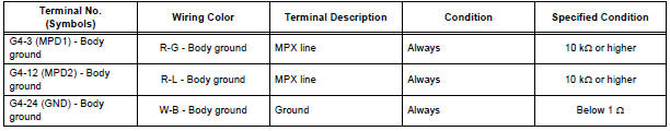
If the result is not as specified, there may be a malfunction on the wire harness side.
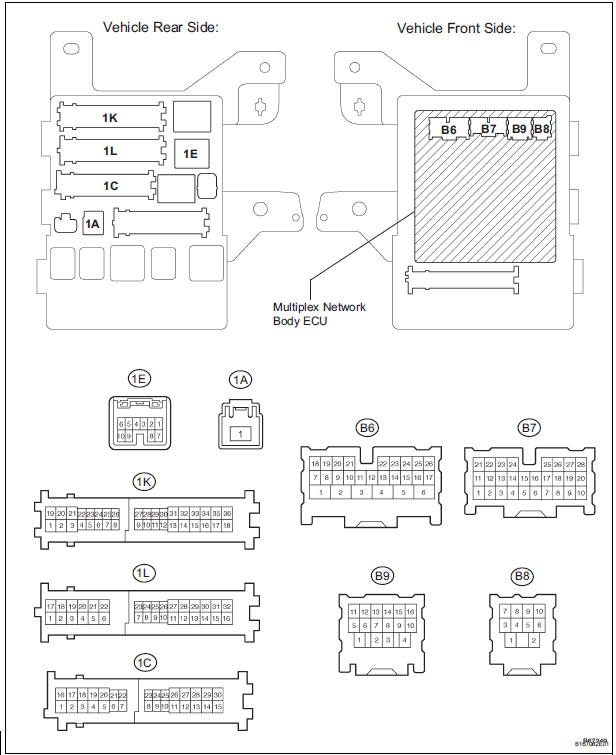
2. MULTIPLEX NETWORK BODY ECU
- Disconnect the B7 ECU, 1A, 1C, 1E, 1K and 1L junction block connectors
- Measure the voltage between the specified terminals on the wire harness side connector.
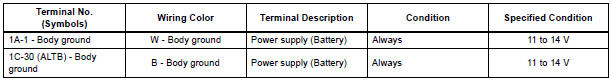
If the result is not as specified, there may be a malfunction on the wire harness side.
- Measure the resistance between the specified terminals on the wire harness side connector
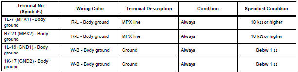
If the result is not as specified, there may be a malfunction on the wire harness side.
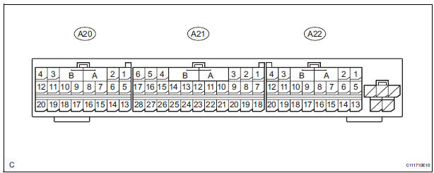
3. AIRBAG SENSOR ASSEMBLY
- Disconnect the A21 ECU connector.
- Measure the voltage between the specified terminals on the wire harness side connector.

If the result is not as specified, there may be a malfunction on the wire harness side.
- Measure the resistance between the specified terminals on the wire harness side connector.
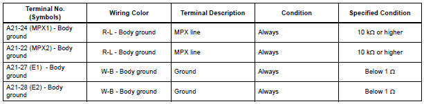
If the result is not as specified, there may be a malfunction on the wire harness side.
4. SEAT POSITION CONTROL ECU (with Driving Position Memory)
- Disconnect the P58 and P59 ECU connectors.
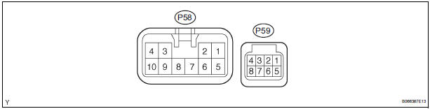
- Measure the voltage between the specified terminals on the wire harness side connector.

If the result is not as specified, there may be a malfunction on the wire harness side.
- Measure the resistance between the specified terminals on the wire harness side connector.
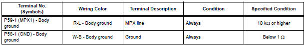
If the result is not as specified, there may be a malfunction on the wire harness side.
5. AIR CONDITIONING AMPLIFIER
- Disconnect the A9 ECU connector.

- Measure the voltage between the specified terminals on the wire harness side connector.
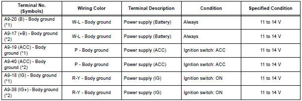
If the result is not as specified, there may be a malfunction on the wire harness side.
- Measure the resistance between the specified terminals on the wire harness side connector.
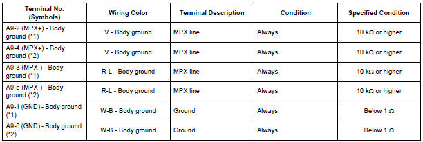
HINT:
*1: for Automatic A/C
*2: for Manual A/C
If the result is not as specified, there may be a malfunction on the wire harness side.
6. COMBINATION METER
- Disconnect the C10 ECU connector.

- Measure the voltage between the specified terminals on the wire harness side connector.
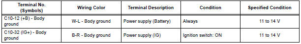
If the result is not as specified, there may be a malfunction on the wire harness side.
- Measure the resistance between the specified terminals on the wire harness side connector.
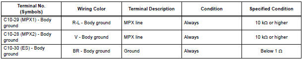
If the result is not as specified, there may be a malfunction on the wire harness side.
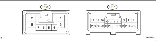
7. POWER SLIDE DOOR ECU RH
- Disconnect the P27 and P28 ECU connectors.
- Measure the voltage between the specified terminals on the wire harness side connector.


If the result is not as specified, there may be a malfunction on the wire harness side.
- Measure the resistance between the specified terminals on the wire harness side connector.
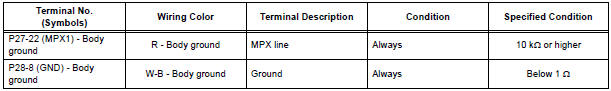
If the result is not as specified, there may be a malfunction on the wire harness side.
8. POWER SLIDE DOOR ECU LH
- Disconnect the P25 and P26 ECU connectors.
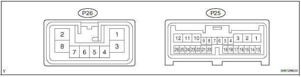
- Measure the voltage between the specified terminals on the wire harness side connector.
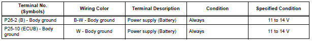
If the result is not as specified, there may be a malfunction on the wire harness side.
- Measure the resistance between the specified terminals on the wire harness side connector.
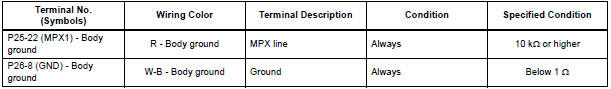
If the result is not as specified, there may be a malfunction on the wire harness side.
9. POWER BACK DOOR ECU
- Disconnect the P13 and P14 ECU connectors.
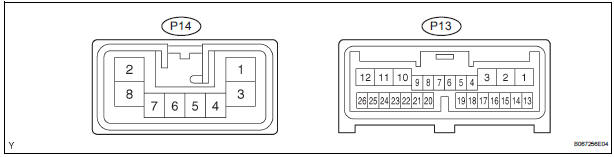
- Measure the voltage between the specified terminals on the wire harness side connector.
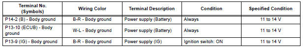
If the result is not as specified, there may be a malfunction on the wire harness side.
- Measure the resistance between the specified terminals on the wire harness side connector.
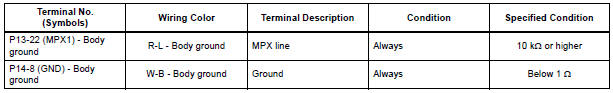
If the result is not as specified, there may be a malfunction on the wire harness side.
10. OUTER MIRROR CONTROL ECU RH (with Driving Position Memory)
- Disconnect the O11 ECU connector.
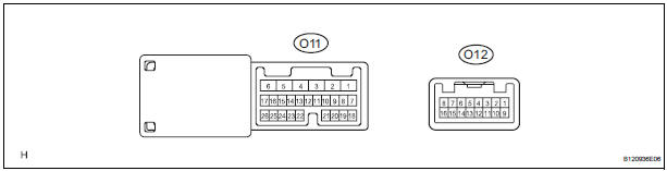
- Measure the voltage between the specified terminals on the wire harness side connector.
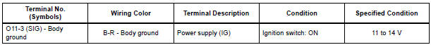
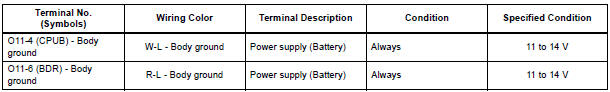
If the result is not as specified, there may be a malfunction on the wire harness side.
- Measure the resistance between the specified terminals on the wire harness side connector.
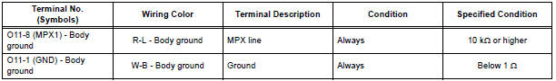
If the result is not as specified, there may be a malfunction on the wire harness side.
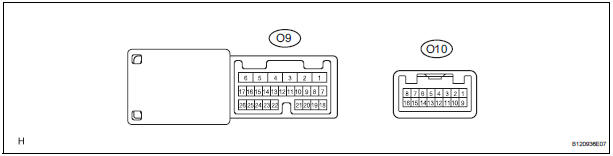
11. OUTER MIRROR CONTROL ECU LH (with Driving Position Memory)
- Disconnect the O9 ECU connector.
- Measure the voltage between the specified terminals on the wire harness side connector.
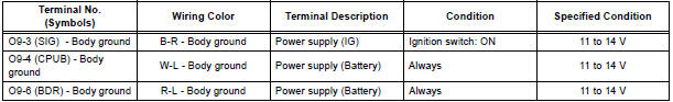
If the result is not as specified, there may be a malfunction on the wire harness side.
- Measure the resistance between the specified terminals on the wire harness side connector
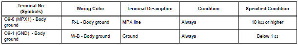
If the result is not as specified, there may be a malfunction on the wire harness side.
 How to proceed with
troubleshooting
How to proceed with
troubleshooting
HINT:
Troubleshoot in accordance with the procedures on the
following pages.
1 VEHICLE BROUGHT TO WORKSHOP
2 DTC CHECK
Check for DTCs and make a note of the code that is
output (See page MP- ...
 DTC check / clear
1. CHECK DTC
Prepare the intelligent tester.
Connect the intelligent tester to DLC3.
Turn the ignition switch to the ON position and turn
the intelligent tester main switch ON.
Use the i ...
Other materials:
Operating the HomeLink
Press the appropriate HomeLink® button. The HomeLink® indicator
light on the HomeLink® transceiver should turn on.
The HomeLink® continues to send a signal for up to 20 seconds as long as
the button is pressed.
Reprogramming a HomeLink® button
Press and hold the desired HomeLink® button ...
How to proceed with
troubleshooting
HINT:
The intelligent tester can be used in steps 2, 3, 4, 6 and 9.
1 VEHICLE BROUGHT TO WORKSHOP
2 CONNECT INTELLIGENT TESTER TO DLC3
HINT:
If the display indicates a communication fault in the tester,
inspect the DLC3.
3 CHECK DTC AND FREEZE FRAME DATA
(a) Check for DTC(s) and freeze f ...
Trouble in Passenger Airbag ON / OFF Indicator
DESCRIPTION
The occupant classification system detects the front passenger seat
condition. It then informs a
passenger of the front passenger airbag, the front seat side airbag RH and front
seat belt pretensioner
RH condition (activated/not activated) by the passenger airbag ON/OFF indicator. ...
