Toyota Sienna Service Manual: Disassembly
1. REMOVE FUEL TANK TO FILLER PIPE HOSE (See page FU-43)
2. REMOVE FUEL TANK MAIN TUBE SUB-ASSEMBLY
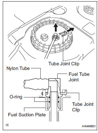
(a) Remove the tube joint clip, and pull out the fuel main tube.
NOTICE:
|
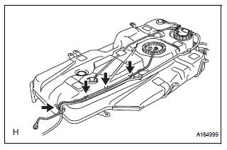
(b) Unfasten the 4 claws and remove the fuel tank main tube from the fuel tank.
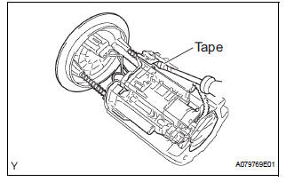
3. REMOVE FUEL SUCTION TUBE ASSEMBLY WITH PUMP AND GAUGE
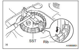
(a) Using SST, loosen the fuel pump gauge retainer.
SST 09808-14020 (09808-01410, 09808-01420, 09808-01430)
HINT: A rib on the fuel pump gauge retainer can be fitted into a tip of SST.
(b) Remove the fuel pump gauge retainer.
(c) Remove the fuel suction tube assembly with pump and gauge and the fuel suction tube set gasket from the fuel tank.
| NOTICE: Be careful not bend the arm of the fuel sender gauge. |
4. REMOVE FUEL SENDER GAUGE ASSEMBLY
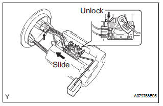
(a) Disconnect the fuel sender gauge connector.
(b) Unlock the fuel sender gauge and slide it to remove.
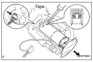
5. REMOVE FUEL SUCTION PLATE SUB-ASSEMBLY
(a) Using a screwdriver with the tip wrapped in tape, disconnect the 4 snap-claws from the claw holes and remove the fuel suction plate.
| NOTICE: Do not damage the fuel suction plate and the No. 1 fuel suction support. |
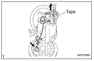
6. REMOVE FUEL PUMP
(a) Disconnect the fuel pump connector.
(b) Using a small screwdriver with the tip wrapped in tape, disconnect the 2 claws from the claw holes and pull out the fuel pump.
| NOTICE: Do not damage the fuel pump and the fuel suction plate. |
(c) Remove the O-ring and the fuel pump spacer from the fuel pump.
7. REMOVE FUEL FILTER ASSEMBLY
(a) Using a small screwdriver, pry out the clip.
(b) Remove the fuel filter assembly from the fuel pump.
8. REMOVE NO. 1 FUEL TUBE JOINT
(a) Remove the connector.
(b) Using a screwdriver with the tip wrapped in tape, disconnect the snap-claw from the claw hole and pull out the No. 1 fuel tube joint.
| NOTICE: Do not damage the No. 1 fuel tube joint and the fuel suction plate. |
9. REMOVE FUEL PUMP HARNESS
(a) Remove the fuel pump harness from the No. 1 fuel tube joint.
10. REMOVE FUEL PRESSURE REGULATOR ASSEMBLY
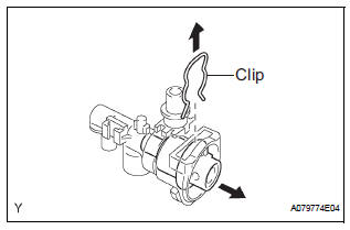
(a) Remove the clip.
(b) Pull out the fuel pressure regulator from the fuel suction plate.
(c) Remove the 2 O-rings from the fuel pressure regulator.
 Removal
1. DISCHARGE FUEL SYSTEM PRESSURE
(See page FU-1)
2. REMOVE CHARCOAL CANISTER PROTECTOR
(a) Remove the 6bolts and the charcoal canister
protector.
3. REMOVE REAR FLOOR NO. 2 CROSSMEMBER
BRACE LH ...
 Inspection
1. INSPECT FUEL PUMP
(a) Inspect fuel pump resistance.
(1) Using an ohmmeter, measure the resistance
between the terminals.
Standard resistance
(b) Inspect fuel pump operation
(1) Apply ...
Other materials:
Installation
1. INSTALL PARKING BRAKE CONTROL PEDAL ASSEMBLY
(a) Install the parking brake control pedal assembly with
a bolt and the 2 nuts.
Torque: 39 N*m (398 kgf*cm, 29 ft.*lbf)
(b) Connect the parking brake switch connector.
(c) Connect the instrument panel junction block
assembly w/ wiring ha ...
Back Door Closer Switch Malfunction
DTC B2215 Back Door Closer Switch Malfunction
DESCRIPTION
This DTC is output when a malfunction occurs in the position switch in the
back door. This position switch
detects if the back door is in the latch position and sends a position signal to
the power back door ECU.
DTC No.
...
Mass or Volume Air Flow Circuit Range / Performance
Problem
DTC P0101 Mass or Volume Air Flow Circuit Range / Performance
Problem
DESCRIPTION
Refer to DTC P0100
DTC No.
DTC Detection Condition
Trouble Area
P0101
High voltage:
Conditions (a), (b) and (c) continue for more than
10 seconds (2 trip de ...
