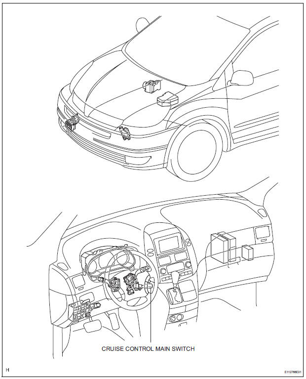
Toyota Sienna Service Manual: Cruise control main switch
COMPONENTS
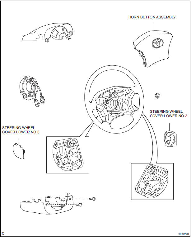
Removal
1. DISCONNECT BATTERY NEGATIVE TERMINAL
2. REMOVE STEERING WHEEL COVER LOWER NO.2 (24)
3. REMOVE STEERING WHEEL COVER LOWER NO.3 (24)
4. REMOVE HORN BUTTON ASSEMBLY
5. REMOVE CRUISE CONTROL MAIN SWITCH
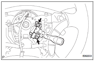
- Disconnect the connectors.
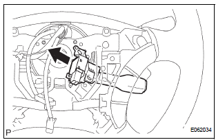
- Remove the 2 screws and cruise control main switch.
Installation
1. INSTALL HORN BUTTON ASSEMBLY
2. INSTALL STEERING WHEEL COVER LOWER NO.3 (25)
3. INSTALL STEERING WHEEL COVER LOWER NO.2 (25)
4. INSPECT SRS WARNING LIGHT
 TC and CG Terminal Circuit
DESCRIPTION
Connecting terminals TC and CG of the DLC3 causes the system to enter the
self-diagnostic mode. If a
malfunction is present, DTCs will be output.
HINT:
When a particular warning ligh ...

Other materials:
Mass or Volume Air Flow Circuit Range / Performance
Problem
DTC P0101 Mass or Volume Air Flow Circuit Range / Performance
Problem
DESCRIPTION
Refer to DTC P0100
DTC No.
DTC Detection Condition
Trouble Area
P0101
High voltage:
Conditions (a), (b) and (c) continue for more than
10 seconds (2 trip de ...
Removal
1. REMOVE REAR SEAT 3 POINT TYPE BELT
ASSEMBLY (for 8-Passenger)
HINT:
Refer to the instructions for disassembly of the rear No. 1
seat assembly (for center seat).
Remove the bolt and rear seat 3 point type belt
assembly.
2. REMOVE REAR SEAT 3 POINT TYPE BELT
ASSEMBLY (for 7-Pass ...
Air conditioning controls
Adjusting the temperature setting
Turn the “TEMP” dial clockwise to increase the temperature and
counterclockwise to decrease the temperature.
The “SYNC” button
The air conditioning system switches between individual (indicator(
s) off) and simultaneous (indicators on) modes.
Whe ...
