Toyota Sienna Service Manual: Terminals of ecu
1. Terminal of ECU
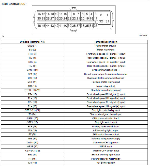
(*1): Models with dynamic laser cruise control (*2): 2WD model
2. Terminal Inspection
(a) Disconnect the connector and measure the voltage or resistance on the wire harness side.
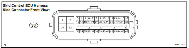
HINT: Voltage cannot be measured with the connector connected to the skid control ECU because the connector is watertight.
Standard 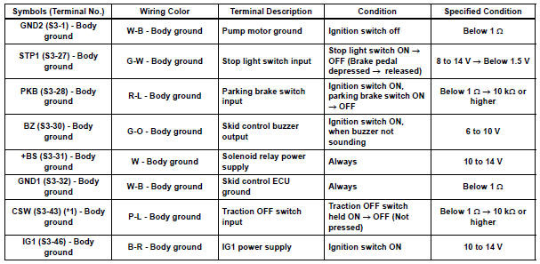
(*1): 2WD model
 Yaw rate sensor check (when using sst check wire)
(a) Check the zero point voltage of the yaw rate sensor.
(1) Keep the vehicle in a stationary condition on a
level surface for 1 second or more.
(b) Check the output of the yaw rate sensor.
...
 Dtc check / clear
1. DTC CHECK/CLEAR (WHEN USING INTELLIGENT TESTER):
(a) DTC check
(1) Connect the intelligent tester to the DLC3.
(2) Turn the ignition switch to the ON position.
(3) Read the DTCs followi ...
Other materials:
Power Source Circuit
DESCRIPTION
Power is supplied to the fold seat control ECU through the L-RR2 SEAT and
R-RR2 SEAT fuses.
WIRING DIAGRAM
INSPECTION PROCEDURE
1 INSPECT FUSE (L-RR2 SEAT, R-RR2 SEAT)
Remove the fuses from the R/B No. 3.
Measure the resistance according to the value(s) in the
...
Throttle Actuator Control Motor Current Range / Performance
DESCRIPTION
The ETCS (Electronic Throttle Control System) has a dedicated power supply
circuit. The voltage (+BM)
is monitored and when it is low (less than 4 V), the ECM determines that there
is a malfunction in the
ETCS and cuts off the current to the throttle actuator.
When the volt ...
Inspection
1. INSPECT FRONT DIFFERENTIAL
(a) Using a dial indicator, measure the backlash of one
pinion gear while holding the front differential side
gear toward the case.
Standard backlash:
0.05 - 0.20 mm (0.0020 - 0.0079 in.)
NOTICE:
Do not mount the surface of front differential
case which cont ...
