Toyota Sienna Service Manual: Yaw rate sensor check (when using sst check wire)
(a) Check the zero point voltage of the yaw rate sensor.
(1) Keep the vehicle in a stationary condition on a level surface for 1 second or more.
(b) Check the output of the yaw rate sensor.
(1) Move the shift lever to the D position, drive the vehicle at a speed of approximately 3 mph (5 km/h), and turn the steering wheel either to the left or right 90° or more until the vehicle makes 180° turn.
(2) Stop the vehicle and move the shift lever to the position. Check that the skid control buzzer sounds for 3 seconds.
HINT:
- If the skid control buzzer sounds, the signal check is completed normally.
- If the skid control buzzer does not sound, check the skid control buzzer circuit, then perform the signal check again.
- If the skid control buzzer does not sound yet, there is a malfunction in the yaw rate sensor, so check the DTC.
- Make a 180° turn. At the end of the turn, the direction of the vehicle should be within 180 +- 5° of its start position.
- Do not spin the wheels.
11. DTC OF TEST MODE (SIGNAL CHECK) FUNCTION
ABS sensor: 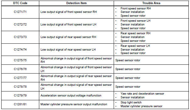
VSC sensor: 
HINT: The codes in this table are output only in Test Mode (signal check).
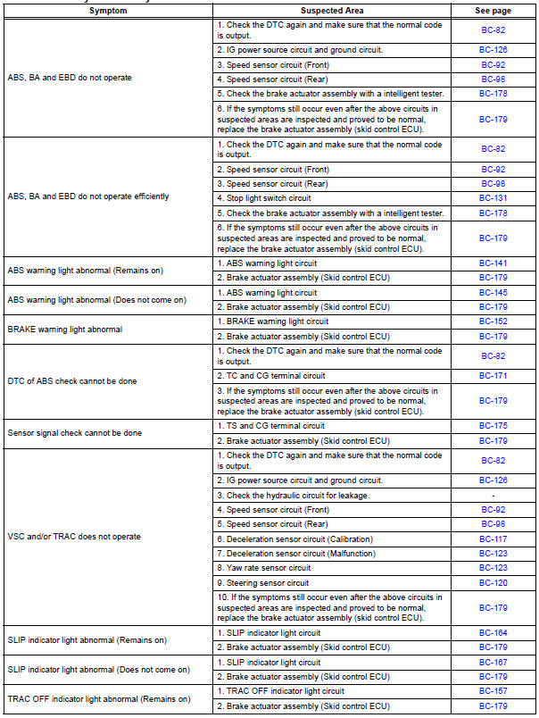
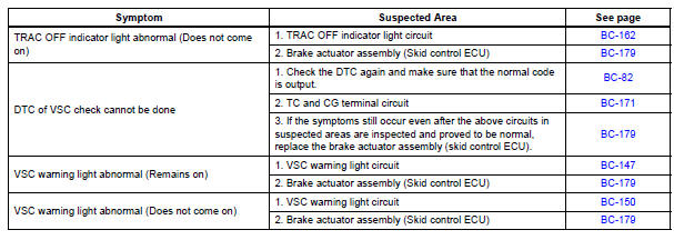
Problem symptoms table
Vehicle Stability Control System:
 Speed sensor check (when using sst check wire)
(a) Check the speed sensor signal.
(1) Drive the vehicle straight forward. Drive the
vehicle at a speed of 45 km/h (28 mph) or higher
for several seconds and check that the ABS
warning light goe ...
 Terminals of ecu
1. Terminal of ECU
(*1): Models with dynamic laser cruise control
(*2): 2WD model
2. Terminal Inspection
(a) Disconnect the connector and measure the voltage
or resistance on the wire harness ...
Other materials:
Adjustment
1. REMOVE REAR WHEEL
2. ADJUST PARKING BRAKE SHOE CLEARANCE (See
page PB-18)
3. INSTALL REAR WHEEL
Torque: 103 N*m (1,050 kgf*cm, 76 ft.*lbf)
4. INSPECT PARKING BRAKE PEDAL TRAVEL
(a) Slowly depress the parking brake pedal all the way,
and count the number of clicks.
Parking brake pedal trav ...
Data list / active test
1. DATA LIST
HINT:
Using the intelligent tester to read the DATA LIST allows
the values or states of switches, sensors, actuators and
other items to be read without removing any parts. This
non-intrusive inspection can be very useful because
intermittent conditions or signals may be discovered ...
Reassembly
NOTICE:
Before installation, coat the parts indicated by arrows
with power steering fluid (See page PS-7).
1. INSTALL VANE PUMP HOUSING OIL SEAL
(a) Coat a new vane pump housing oil seal lip with
power steering fluid.
(b) Using SST and a press, install the vane pump
housing oil seal until i ...
