Toyota Sienna Service Manual: Accelerator pedal rod
COMPONENTS
ON-VEHICLE INSPECTION
1. CHECK ACCELERATOR PEDAL ROD
(a) Check the voltage.
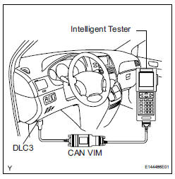
(1) Connect the intelligent tester to the DLC3.
(2) Turn the ignition switch to the ON position.
(3) Turn the intelligent tester on.
(4) Select the menu items: DIAGNOSIS / ENHANCED OBD II / DATA LIST / ALL / ACCEL POS #1, ACCEL POS #2.
(5) Operate the accelerator pedal, and then check that the ACCEL POS #1 and ACCEL POS #2 values are within the specifications.
Standard voltage (ACCEL POS #1)
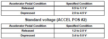
If the result is not as specified, check the accelerator pedal rod, wire harness or ECM.
REMOVAL
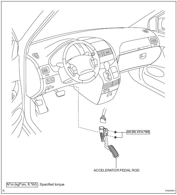
1. REMOVE ACCELERATOR PEDAL ROD
(a) Disconnect the accelerator pedal position sensor connector.
(b) Remove the 2 nuts and accelerator pedal rod.
INSTALLATION
1. INSTALL ACCELERATOR PEDAL ROD
NOTICE:
|
(a) Install the accelerator pedal rod with the 2 nuts.
Torque: 4.9 N*m (50 kgf*cm, 43 in.*lbf) (b) Connect the accelerator pedal position sensor connector.
 ECM
ECM
COMPONENTS
REMOVAL
1. REMOVE GLOVE COMPARTMENT DOOR ASSEMBLY
(a) Push the right side wall and then push the left wall
to release the stoppers.
(b) Pull the glove compartment door sub-as ...
 Mass air flow meter
COMPONENTS
ON-VEHICLE INSPECTION
1. INSPECT MASS AIR FLOW METER
NOTICE:
Perform the mass air flow (MAF) meter inspection
by following the procedures below.
Only replace t ...
Other materials:
Installation
1. INSTALL VANE PUMP ASSEMBLY
(a) Temporarily install the bolt to the vane pump
assembly.
(b) Install the vane pump assembly.
(c) Temporarily install the bolt (B).
(d) Using SST, tighten the 2 bolts.
SST 09249-63010
Torque:Without SST
43 N*m (439 kgf*cm, 32 ft.*lbf)
With SST
29 ...
Removal
1. DISCONNECT CABLE FROM NEGATIVE BATTERY
TERMINAL
2. REMOVE FRONT BUMPER ASSEMBLY
Remove the 4 screws and separate the fender liner
from the front bumper assembly.
Remove the 8 screws and separate the engine
under cover from the front bumper assembly.
Remove the 5 ...
Personal/interior
lights
Front
Turns the light on/off
Rear
Turns the light on/off
When the personal/interior light main switch is in the off position, the
rear personal lights will not turn on even if the switch is on.
Type A
Type B
...
