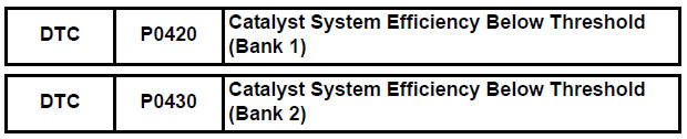
Toyota Sienna Service Manual: Catalyst System Efficiency Below Threshold
MONITOR DESCRIPTION
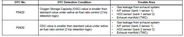
The ECM uses the sensors mounted in front of and behind the three-way catalyst (TWC) to monitor its efficiency. The first sensor, an Air Fuel ratio (A/F) sensor, sends pre-catalyst A/F ratio information to the ECM. The second sensor, a heated oxygen sensor (O2S), sends post-catalyst information to the ECM.
The ECM compares these 2 signals to judge the efficiency of the catalyst and the catalyst's ability to store oxygen. During normal operation, the TWC stores and releases oxygen as needed. The capacity to store oxygen results in a low variation in the post-TWC exhaust stream.
If the catalyst is functioning normally, the waveform of the heated oxygen sensor slowly switches between RICH and LEAN. If the catalyst is deteriorated, the waveform will alternate frequently between RICH and LEAN. As the catalyst efficiency degrades, its ability to store oxygen is reduced and the catalyst output becomes more variable. When running the monitor, the ECM compares sensor 1 signals (A/F sensor) over a specific amount of time to determine catalyst efficiency. The ECM begins by calculating the signal length for both sensors (for the rear oxygen sensor, the ECM uses the output voltage signal length). If the oxygen sensor output voltage signal length is greater than the threshold (threshold is calculated based on the A/F sensor signal length), the ECM concludes that the catalyst is malfunctioning. The ECM will turn on the MIL and a DTC will be set.
HINT:
- Bank 1 refers to the bank that includes cylinder No. 1.
- Bank 2 refers to the bank that does not include cylinder No. 1.
- Sensor 1 refers to the sensor closest to the engine assembly
- Sensor 2 refers to the sensor farthest away from the engine assembly.
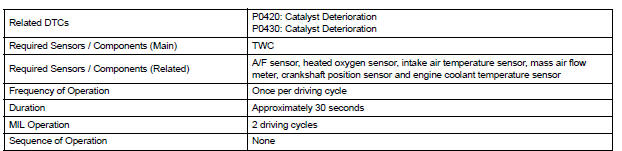
MONITOR STRATEGY
TYPICAL ENABLING CONDITIONS
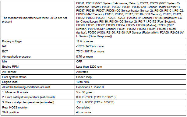
TYPICAL MALFUNCTION THRESHOLDS

MONITOR RESULT
Refer to CHECKING MONITOR STATUS (See page ES-19).
CONDITIONING FOR SENSOR TESTING
HINT:
Perform the operation with the engine speeds and durations described below prior to checking the waveforms of the A/F and HO2 sensors. This is in order to activate the sensors sufficiently to obtain the appropriate inspection results.
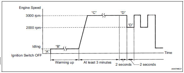
1. Connect the intelligent tester to the DLC3 (Procedure "A").
2. Start the engine and warm it up with all the accessories switched off, until the engine coolant temperature stabilizes (Procedure "B").
3. Run the engine at an engine speed of between 2500 rpm and 3000 rpm for at least 3 minutes (Procedure "C").
4. While running the engine at 3000 rpm for 2 seconds and at 2000 rpm for 2 seconds, check the waveforms of the A/F and HO2 sensors using the tester (Procedure "D").
HINT:
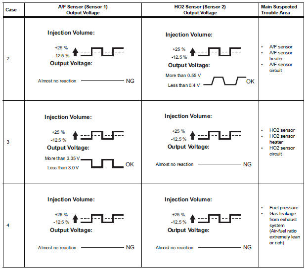
- If either of the voltage outputs of the Air-Fuel Ratio (A/F) or Heated Oxygen (HO2) sensor does not fluctuate, or either of the sensors makes a noise, the sensor may be malfunctioning.
- If the voltage outputs of both the sensors remain lean or rich, the air-fuel ratio may be extremely lean or rich. In such cases, perform the following A/F CONTROL using the intelligent tester.
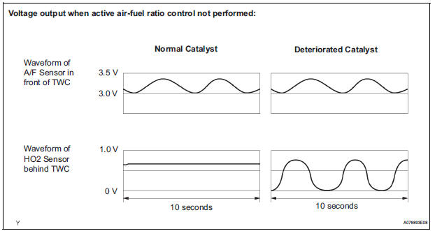
- If the Three-Way Catalytic Converter (TWC) has deteriorated, the HO2 sensor (located behind the TWC) voltage output fluctuates up and down frequently, even under normal driving conditions (active air-fuel ratio control is not performed).
1. A/F CONTROL
HINT:
Intelligent tester only: Malfunctioning areas can be identified by performing the A/F CONTROL function provided in the ACTIVE TEST. The A/F CONTROL function can help to determine whether the Air-Fuel Ratio (A/F) sensor, Heated Oxygen (HO2) sensor and other potential trouble areas are malfunctioning.
The following instructions describe how to conduct the A/F CONTROL operation using an intelligent tester.
(a) Connect the intelligent tester to the DLC3.
(b) Start the engine and turn the tester on.
(c) Warm up the engine at an engine speed of 2500 rpm for approximately 90 seconds.
(d) On the tester, select the following menu items: DIAGNOSIS / ENHANCED OBD II / ACTIVE TEST / A/F CONTROL.
(e) Perform the A/F CONTROL operation with the engine in an idling condition (press the RIGHT or LEFT button to change the fuel injection volume).
(f) Monitor the voltage outputs of the A/F and HO2 sensors (AFS B1S1 and O2S B1S2 or AFS B2S1 and O2S B2S2) displayed on the tester.
HINT:
- The A/F CONTROL operation lowers the fuel injection volume by 12.5% or increases the injection volume by 25%.
- Each sensor reacts in accordance with increases and decreases in the fuel injection volume.
Standard voltage 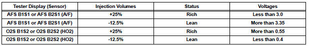
| CAUTION: The Air-Fuel Ratio (A/F) sensor has an output delay of a few seconds and the Heated Oxygen (HO2) sensor has a maximum output delay of approximately 20 seconds. |
- Following the A/F CONTROL procedure enables technicians to check and graph the voltage outputs of both the A/F and HO2 sensors.
- To display the graph, select the following menu items on the tester: DIAGNOSIS / ENHANCED OBD II / ACTIVE TEST / A/F CONTROL / USER DATA / AFS B1S1 and O2S B1S2 or AFS B2S1 and O2S B2S2. Press the YES button and then the ENTER button. Then press the F4 button.
INSPECTION PROCEDURE
HINT:
Read freeze frame data using the intelligent tester. The ECM records vehicle and driving condition information as freeze frame data the moment a DTC is stored. When troubleshooting, freeze frame data can be helpful in determining whether the vehicle was running or stopped, whether the engine was warmed up or not, whether the air-fuel ratio was lean or rich, as well as other data recorded at the time of a malfunction.
1 CHECK ANY OTHER DTCS OUTPUT (IN ADDITION TO DTC P0420 AND/OR P0430)
(a) Connect the intelligent tester to the DLC3.
(b) Turn the ignition switch to the ON position and turn the tester on.
(c) Select the following menu items: DIAGNOSIS / ENHANCED OBD II / DTC INFO / CURRENT CODES.
(d) Read the DTCs.
Result 
HINT:
If any DTCs other than P0420 or P0430 are output, troubleshoot those DTCs first.


2 PERFORM ACTIVE TEST BY INTELLIGENT TESTER (A/F CONTROL)
(a) Connect the intelligent tester to the DLC3.
(b) Start the engine and turn the tester on.
(c) Warm up the engine at an engine speed of 2500 rpm for approximately 90 seconds.
(d) Select the following menu items on the tester: DIAGNOSIS / ENHANCED OBD II / ACTIVE TEST / A/F CONTROL.
(e) Perform the A/F CONTROL operation with the engine in an idling condition (press the RIGHT or LEFT button to change the fuel injection volume).
(f) Monitor the voltage outputs of the A/F and HO2 sensors (AFS B1S1 and O2S B1S2 or AFS B2S1 and O2S B2S2) displayed on the tester.
HINT:
- The A/F CONTROL operation lowers the fuel injection volume by 12.5% or increases the injection volume by 25%.
- Each sensor reacts in accordance with increases and decreases in the fuel injection volume.
Standard voltage 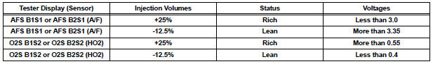
Result 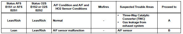
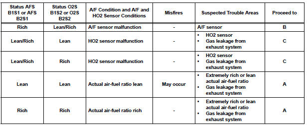
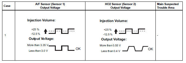
Lean: During A/F CONTROL, the A/F sensor output voltage (AFS) is consistently more than 3.35 V, and the HO2 sensor output voltage (O2S) is consistently less than 0.4 V.
Rich: During A/F CONTROL, the AFS is consistently less than 3.0 V, and the O2S is consistently more than 0.55 V.
Lean/Rich: During A/F CONTROL of the ACTIVE TEST, the output voltage of the HO2 sensor alternates correctly.

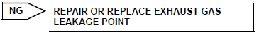
3 INSPECT FOR EXHAUST GAS LEAK
OK: No gas leakage.

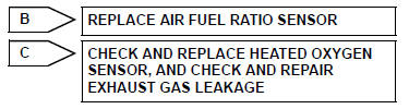
REPLACE THREE-WAY CATALYTIC CONVERTER (EXHAUST MANIFOLD LH OR RH)
 Camshaft Position Sensor "B" Circuit
DESCRIPTION
The exhaust camshaft's Variable Valve Timing (VVT) sensor consists of a
magnet and MRE (Magneto
Resistance Element).
The exhaust camshaft has a sensor plate with 3 teeth on its ...
 Evaporative Emission System Reference Orifice
DTC SUMMARY
HINT:
The 0.02 inch orifice is located inside the pump module.
DESCRIPTION
The circuit description can be found in the EVAP (Evaporative Emission)
System (See page ES-409).
...
Other materials:
Mute Signal Circuit between Radio and Navigation Assembly and
Television Display Assembly
DESCRIPTION
The radio and navigation assembly controls the volume according to the MUTE
signal from the television
display assembly.
The MUTE signal is sent to reduce noise and a popping sound generated when
switching the mode, etc.
If there is an open in the circuit, noise can be heard ...
Pressure Control Solenoid "D" Performance (Shift
Solenoid Valve SLT)
SYSTEM DESCRIPTION
The linear solenoid valve (SLT) controls the transmission line pressure for
smooth transmission operation
based on signals from the throttle position sensor and the vehicle speed sensor.
The ECM adjusts the
duty ratio (*) of the SLT solenoid valve to control hydraulic line ...
Removal
1. PRECAUTION
HINT:
See page RS-1
2. SEPARATE BATTERY NEGATIVE TERMINAL
3. PLACE FRONT WHEELS FACING STRAIGHT AHEAD
4. REMOVE HORN BUTTON ASSEMBLY (See page RS-
424)
5. REMOVE STEERING WHEEL ASSEMBLY (See page
SR-6)
6. REMOVE STEERING COLUMN COVER LWR (See
page RS-434)
7. REMOVE SPIRAL CA ...
