Toyota Sienna Service Manual: Terminals of ECU
1. TELEVISION DISPLAY ASSEMBLY
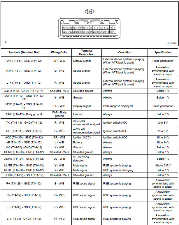
*1: with Navigation System
- A Remote Control System does not Operate
- Sound Signal Circuit between Video Terminal and Television Display
- Display Signal Circuit between Video Terminal and Television Display
- Television Display Power Source Circuit
 Problem symptoms table
HINT:
Inspect the "Fuse" and "Relay" before confirming the
suspected area as shown in the table below.
DISPLAY FUNCTION:
SOUND FUNCTION:
REMOTE CONTROL FUNCTION:
...
 A Remote Control System does not Operate
INSPECTION PROCEDURE
1 CHECK SYSTEM
Check that the remote control operation of the rear
system is not locked by the radio receiver or the radio
and navigation assembly.
Check ...
Other materials:
License plate light assembly
COMPONENTS
REMOVAL
1. REMOVE BACK DOOR GARNISH CENTER
2. REMOVE BACK DOOR SIDE GARNISH LH
3. REMOVE BACK DOOR SIDE GARNISH RH
4. REMOVE BACK DOOR STRAP COVER
5. REMOVE BACK DOOR PULL STRAP
6. REMOVE BACK DOOR TRIM BOARD ASSEMBLY
7. REMOVE BACK DOOR GARNISH SUB-ASSEMBLY OUTSIDE
8. RE ...
Removal
1. REMOVE FRONT DOOR LOWER FRAME BRACKET GARNISH
2. REMOVE FRONT DOOR INSIDE HANDLE BEZEL PLUG
3. REMOVE FRONT DOOR ARMREST BASE PANEL
ASSEMBLY
4. REMOVE BACK FRAME PLATE
5. REMOVE POWER WINDOW REGULATOR MASTER SWITCH ASSEMBLY
6. REMOVE FRONT DOOR TRIM BOARD SUBASSEMBLY
7. REMOVE OUTER RE ...
Data list / active test
1. DATA LIST
HINT:
With the intelligent tester connected to the DLC3 and the
ignition switch to the ON position, the ABS, TRAC and
VSC data list can be displayed. Follow the prompts on
the tester screen to access the DATA LIST.
*: 2WD
2. ACTIVE TEST
HINT:
Performing the ACTIVE TEST usin ...
