Toyota Sienna Service Manual: Display Signal Circuit between Video Terminal and Television Display
DESCRIPTION
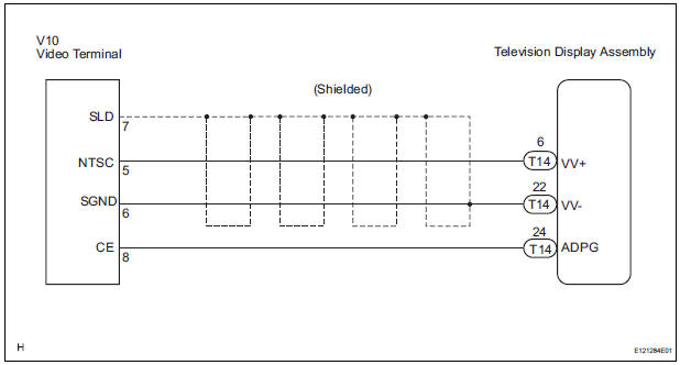
This is the display signal circuit from the video terminal to the television display assembly.
WIRING DIAGRAM
INSPECTION PROCEDURE
1 CHECK HARNESS AND CONNECTOR (TELEVISION DISPLAY ASSEMBLY - VIDEO TERMINAL)
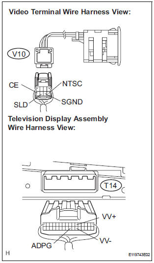
- Disconnect the connectors from the video terminal and television display assembly.
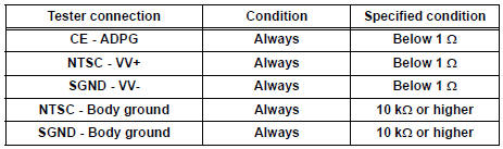
- Measure the resistance according to the value(s) in the table below.
Standard resistance
2 INSPECT VIDEO TERMINAL
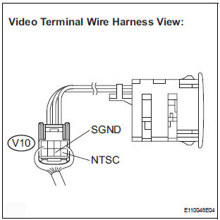
- Reconnect the video (video adapter) terminal connector.
- Measure the waveform according to the table below.
OK
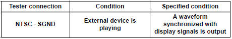
HINT: The waveform pattern may differ from that shown in the illustration below due to differences in oscilloscope setting. A normal video terminal operating condition can be determined if any waveform is output.
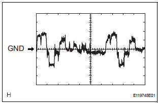
- Oscilloscope waveform
- Terminal: NTSC - Body ground
Setting: 200mV/DIV, 10 μs/DIV
Condition: DVD display is ON.
PROCEED TO NEXT CIRCUIT INSPECTION SHOWN IN PROBLEM SYMPTOMS TABLE
 Sound Signal Circuit between Video Terminal and Television Display
DESCRIPTION
This is the sound signal circuit from the video (video adapter) terminal to
the television display assembly.
WIRING DIAGRAM
INSPECTION PROCEDURE
1 CHECK HARNESS AND CONNECTOR (TE ...
 Television Display Power Source Circuit
DESCRIPTION
This is the power source circuit to operate the television display assembly.
WIRING DIAGRAM
INSPECTION PROCEDURE
1 INSPECT TELEVISION DISPLAY ASSEMBLY
Disconnect the connec ...
Other materials:
ECM Communication Circuit Malfunction
DTC C1203/53 ECM Communication Circuit Malfunction
DESCRIPTION
The circuit is used to send TRAC and VSC control information from the skid
control ECU to the ECM, and
engine control information from the ECM to the skid control ECU through the CAN
communication
system.
INSPECTION PROCEDURE
1 ...
Installation
1. INSTALL REAR SEAT 3 POINT TYPE BELT
ASSEMBLY (for 8-Passenger)
HINT:
Refer to the instructions for reassembly of the rear No. 1
seat assembly (for center seat).
Install the rear seat 3 point type belt assembly with
the bolt.
Torque: 42 N*m (430 kgf*cm, 31 ft.*lbf)
2. INSTALL ...
Intake Air Temperature Circuit
DESCRIPTION
The Intake Air Temperature (IAT) sensor, mounted on the Mass Air Flow (MAF)
meter, monitors the IAT.
The IAT sensor has a built-in thermistor with a resistance that varies according
to the temperature of the
intake air. When the IAT is low, the resistance of the thermistor i ...
