Toyota Sienna Service Manual: Television Display Power Source Circuit
DESCRIPTION
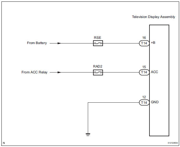
This is the power source circuit to operate the television display assembly.
WIRING DIAGRAM
INSPECTION PROCEDURE
1 INSPECT TELEVISION DISPLAY ASSEMBLY
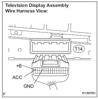
- Disconnect the connector from the television display assembly.
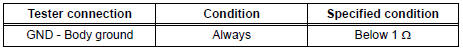
- Measure the resistance according to the value(s) in the table below.
Standard resistance
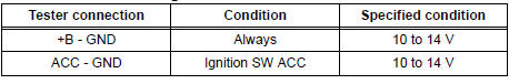
- Measure the voltage according to the value(s) in the table below.
Standard voltage
PROCEED TO NEXT CIRCUIT INSPECTION SHOWN IN PROBLEM SYMPTOMS TABLE
 Display Signal Circuit between Video Terminal and Television Display
DESCRIPTION
This is the display signal circuit from the video terminal to the television
display assembly.
WIRING DIAGRAM
INSPECTION PROCEDURE
1 CHECK HARNESS AND CONNECTOR (TELEVISION DISPL ...
 Radio receiver
COMPONENTS
...
Other materials:
Removal
1. REMOVE REAR SEAT 3 POINT TYPE BELT
ASSEMBLY (for 8-Passenger)
HINT:
Refer to the instructions for disassembly of the rear No. 1
seat assembly (for center seat).
Remove the bolt and rear seat 3 point type belt
assembly.
2. REMOVE REAR SEAT 3 POINT TYPE BELT
ASSEMBLY (for 7-Pass ...
Reassembly
1. INSTALL OVERDRIVE DIRECT CLUTCH O-RING
(a) Coat an O-ring with ATF, and install it to the direct
clutch drum.
NOTICE:
Make sure that the O-ring is not twisted or
pinched when it is installed.
2. INSTALL OVERDRIVE DIRECT CLUTCH DRUM SUBASSEMBLY
(a) Coat the direct clutch drum with A ...
If the engine will not
start
If the engine will not start even though correct starting procedures
are being followed (, 228), consider each of the following
points:
The engine will not start even though the starter motor operates
normally.
One of the following may be the cause of the problem:
There may not be sufficien ...
