Toyota Sienna Service Manual: Transfer system
PRECAUTION
NOTICE:
1. Before disassembly, clean the transfer assembly of any sand or mud to prevent it from entering inside the transfer during disassembly and assembly.
2. When removing any light alloy part such as a transfer cover, do not pry it off with a tool like a screwdriver, but tap it out with a plastic hammer instead.
3. Always arrange the removed parts properly and protect them from dust.
4. Before installation, clean and dry all parts completely, and then apply hypoid gear oil to each part. Do not use alkaline chemicals when cleaning aluminum, rubber parts, or ring gear set bolts. Also do not use any cleaning oil (ex. white gasoline) to clean the rubber parts such as O-rings and oil seals.
5. Apply hypoid gear oil to any sliding surface or rotating part.
6. Do not directly hold a part in a vise. Make sure to put an aluminum sheet between them.
7. Replace any damaged or deformed snap ring with a new one.
8. If there is a scratch on the contact surface of the case, it may cause oil leakage. Therefore, be careful not to to damage the contact surface when handling it.
9. Before applying a sealant, completely remove any old sealant stuck on the parts and clean with white gasoline.
10.Do not add oil immediately after installing sealed parts. Leave for 1 hour or more 11.Scratches on a contact surface of an oil seal, O-ring or gasket may cause oil leakage. Be careful not to damage the contact surface when handling the seals.
12.When press-fitting an oil seal, be careful not to damage the oil seal lip and around it.
13.When replacing a bearing, replace the inner and outer races as a set.
PROBLEM SYMPTOMS TABLE
Transfer system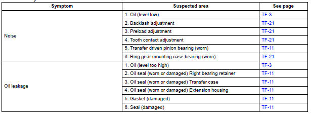
 Transfer
...
 Transfer oil
ON-VEHICLE INSPECTION
1. INSPECT TRANSFER OIL
(a) Remove the No. 1 plug and gasket.
(b) Check the oil level is within 0 - 5 mm (0 - 0.20 in.)
below the lowest end of the hole for No. 1 plug. ...
Other materials:
Problem symptoms table
HINT:
Inspect the fuse and relay before confirming the suspected
areas in the table below.
Inspect each suspected area in numerical order for the
corresponding symptom.
If the malfunction still exists after checking and confirming
that all circuits and components are normal ...
Reassembly
1. INSTALL BACK DOOR STOPPER LOWER
Install the 2 stoppers with the 4 bolts.
Torque: 7.0 N*m (71 kgf*cm, 62 in.*lbf)
2. INSTALL BACK DOOR BASE STOPPER BRACKET
Install the 2 stopper brackets with the 4 bolts.
Torque: 7.0 N*m (71 kgf*cm, 62 in.*lbf)
3. INSTALL BACK DOOR LOCK ASSEMBLY
...
If you think something is
wrong
If you notice any of the following symptoms, your vehicle probably
needs adjustment or repair. Contact your Toyota dealer as
soon as possible.
Visible symptoms
Fluid leaks under the vehicle
(Water dripping from the air conditioning after use is normal.)
Flat-looking tires or uneven tire w ...
