Toyota Sienna Service Manual: Master Error
DTC 01-DF Master Error
DESCRIPTION
|
DTC No. |
DTC Detection Condition |
Trouble Area |
|
01-DF *1 |
The device with a display fails and the master is
switched to the audio device.
Also when a communication error between sub-master (audio) and master occurs, this code is stored |
|
HINT: *1: When 210 seconds have elapsed after disconnecting the power supply connector of the master component with the ignition switch in the ACC or ON position, this code is stored.
NOTICE:
- Before starting troubleshooting, be sure to clear DTCs to erase codes stored due to the reasons described in the HINT above. Then, check for DTCs and troubleshoot according to the output DTCs.
- The radio receiver is the master unit.
- Be sure to clear and recheck DTCs after the inspection is completed to confirm that no DTCs are output.
INSPECTION PROCEDURE
NOTICE: Be sure to read DESCRIPTION before performing the following procedures.
1 CHECK RADIO RECEIVER POWER SOURCE CIRCUIT
Refer to the radio receiver power source circuit.
If the power source circuit is operating normally, proceed to the next step.
2 INSPECT RADIO RECEIVER
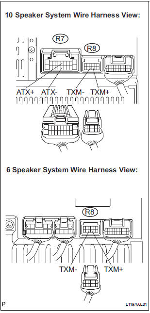
- Disconnect the radio receiver connectors.
- Measure the resistance according to the value(s) in the table below.
Standard resistance
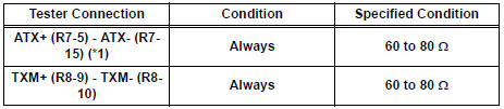
*1: 10 Speaker System
3 IDENTIFY THE COMPONENT WHICH HAS STORED THIS CODE
- Enter the diagnostic mode.
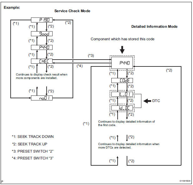
- Press the preset switch "3" to change to "Detailed Information Mode".
- Identify the component which has stored this code.
Component Table:

HINT:
- "440 (stereo component amplifier)" is the component which has stored this code in the example shown in the illustration.
- For details of the DTC display, refer to "DTC CHECK/ CLEAR"
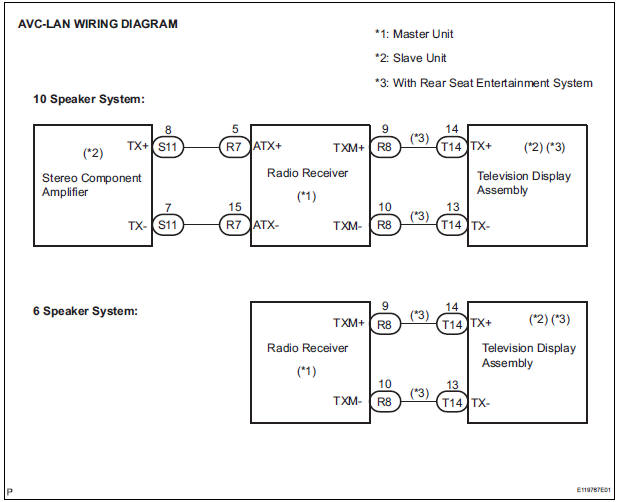
4 CHECK HARNESS AND CONNECTOR (RADIO RECEIVER - COMPONENT WHICH HAS STORED THIS CODE)
HINT: For details of the connectors, refer to the "TERMINALS OF ECU".
- Referring to the AVC-LAN wiring diagram below, check the AVC-LAN circuit between the radio receiver and the component which has stored this code.
- Disconnect all connectors between the radio receiver and the component which has stored this code.
- Check for an open or short in the AVC-LAN circuit between the radio receiver and the component which has stored this code.
OK: There is no open or short circuit.
5 REPLACE RADIO RECEIVER
- Replace the radio receiver with a normal one and check if the same problem occurs again.
OK: Same problem does not occur.
END
 Master Reset/ Voice Processing Device ON Error
DTC 01-DD Master Reset
DTC 01-E1 Voice Processing Device ON Error
DESCRIPTION
HINT:
*1: This code may be stored if the engine is started and the ignition switch is
turned to START position
...
 Registration Complete Indication Error/ Registration Demand Transmission/
Multiple Frame Incomplete
Registration Complete Indication Error/ Registration Demand Transmission/
Multiple Frame Incomplete
DTC 01-E0 Registration Complete Indication Error
DTC 01-E3 Registration Demand Transmission
DTC 01-E4 Multiple Frame Incomplete
DESCRIPTION
DTC No.
DTC Detection Condition
...
Other materials:
Disassembly
1. INSPECT PACK CLEARANCE OF REVERSE CLUTCH
HINT:
(See page AX-249)
2. INSPECT PACK CLEARANCE OF DIRECT CLUTCH
AND OVERDRIVE CLUTCH
HINT:
(See page AX-249)
3. REMOVE DIRECT MULTIPLE DISC CLUTCH DISC
(a) Using a screwdriver, remove the snap ring from the
intermediate shaft.
(b) Remo ...
Power easy access system
The seat is automatically adjusted to allow the driver to enter and exit
the vehicle easily.
When all of the following have
been performed, the driver’s seat
is automatically adjusted to a
position that allows driver to enter
and exit the vehicle easily.
The shift lever has been sh ...
Camshaft Position Sensor "B" Circuit
DESCRIPTION
The exhaust camshaft's Variable Valve Timing (VVT) sensor consists of a
magnet and MRE (Magneto
Resistance Element).
The exhaust camshaft has a sensor plate with 3 teeth on its outer circumference.
When the exhaust camshaft rotates, changes occur in the air gaps between the ...
