Toyota Sienna Service Manual: Actuator Supply Voltage Circuit / Open
DTC P0657 Actuator Supply Voltage Circuit / Open
DESCRIPTION
The ECM monitors the output voltage to the throttle actuator. This self-check ensures that the ECM is functioning properly. The output voltage is usually 0 V when the ignition switch is turned off. If the output voltage is higher than 7 volts when the ignition switch is turned off, the ECM will illuminate the MIL and set a DTC when the ignition switch is turned on.

MONITOR STRATEGY
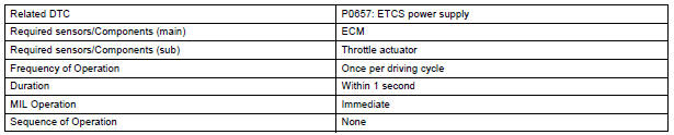
TYPICAL ENABLING CONDITIONS

TYPICAL MALFUNCTION THRESHOLDS

INSPECTION PROCEDURE
1 CHECK WHETHER DTC OUTPUT RECURS (IN ADDITION TO DTC P0657)
- Connect the intelligent tester to the DLC3.
- Turn the ignition switch to the ON position.
- Turn the tester on.
- Clear the DTC.
- Turn the ignition switch off.
- Disconnect the battery negative terminal and wait for 1 minute.
- Connect the battery negative terminal.
- Turn the ignition switch to the ON position for 10 seconds.
- Turn the ignition switch off.
- Turn the ignition switch to the ON position.
- Enter the following menus: DIAGNOSIS / ENHANCED II / DTC INFO / CURRENT CODES.
- Read the DTCs.
Result
REPLACE ECM
 VIN not Programmed or Mismatch - ECM / PCM
DTC P0630 VIN not Programmed or Mismatch - ECM / PCM
DESCRIPTION
DTC P0630 is set when the Vehicle Identification Number (VIN) is not stored
in the Engine Control Module
(ECM) or the input VIN is ...
 Transmission Range Sensor Circuit Malfunction
(PRNDL Input)
Transmission Range Sensor Circuit Malfunction
(PRNDL Input)
DTC P0705 Transmission Range Sensor Circuit Malfunction
(PRNDL Input)
DESCRIPTION
The park/neutral position switch detects the shift lever position and sends
signals to the ECM.
HINT:
After ...
Other materials:
Rear Occupant Classification Sensor LH Circuit
Malfunction
DTC B1782 Rear Occupant Classification Sensor LH Circuit
Malfunction
DESCRIPTION
The rear occupant classification sensor LH circuit consists of the occupant
classification ECU and the rear
occupant classification sensor LH.
DTC B1782 is recorded when a malfunction is detected in the rear oc ...
Evaporative Emission System Switching Valve Control Circuit High
DTC SUMMARY
DESCRIPTION
The circuit description can be found in the EVAP (Evaporative Emission)
System (See page ES-404).
INSPECTION PROCEDURE
Refer to the EVAP System (See page ES-404).
MONITOR DESCRIPTION
5 hours*1 after the ignition switch is turned off, the electric vacuum pump
...
Rear wheel alignment
ADJUSTMENT
NOTICE:
For vehicles equipped with VSC, if wheel alignment has
been adjusted, and if suspension or underbody
components have been removed/installed or replaced, be
sure to perform the following initialization procedure in
order for the system to function normally:
1. Disconnect the ...
