Toyota Sienna Service Manual: A/F sensor and ho2s monitors
(a) Preconditions
The monitor will not run unless:
- 2 minutes or more have elapsed since the engine was started.
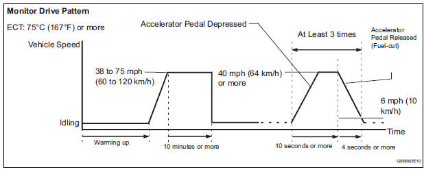
- The Engine Coolant Temperature (ECT) is 75°C (167°F) or more.
- Cumulative driving time at a vehicle speed of 30 mph (48 km/h) or more exceeds 6 minutes.
- Air-fuel ratio feedback control is performed.
- Fuel-cut control is performed for 8 seconds or more (for the Rear HO2 Sensor Monitor).
(b) Drive Pattern for front A/F sensor and HO2 sensor
(1) Connect an intelligent tester to the DLC3.
(2) Turn the ignition switch to the ON position.
(3) Turn the tester ON.
(4) Clear the DTCs.
(5) Start the engine, and warm it up until the ECT reaches 75°C (167°F) or higher.
(6) Drive the vehicle at 38 mph (60 km/h) or more for at least 10 minutes.
(7) Change the transmission to the 2nd gear.
(8) Accelerate the vehicle to 40 mph (64 km/h) or more by depressing the accelerator pedal for at least 10 seconds (Procedure "A").
(9) Soon after performing procedure "A" above, release the accelerator pedal for at least 4 seconds without depressing the brake pedal, in order to execute fuel-cut control (Procedure "B").
(10) Allow the vehicle to decelerate until the vehicle speed declines to less than 6 mph (10 km/h) (Procedure "C").
(11) Repeat procedures from "A" through "C" above at least 3 times in one driving cycle.
(c) Monitor Status
(1) Check the Readiness Monitor status displayed on the tester.
(2) If the status does not switch to COMPL (complete), make sure that the preconditions have been met and then perform the Drive Pattern again.
 Evap monitor (key-off type)
(a) Preconditions
The monitor will not run unless:
The fuel tank is less than 90% full.
The altitude is less than 8000 ft (2450 m).
The vehicle is stationary.
The engine coolant temperature ...
 Air-fuel ratio (a/f) and heated oxygen (ho2)
sensor heater monitors (front a/f and rear ho2 sensor
type)
Air-fuel ratio (a/f) and heated oxygen (ho2)
sensor heater monitors (front a/f and rear ho2 sensor
type)
(a) Preconditions
The monitor will not run unless:
The MIL is OFF.
(b) Drive Pattern
(1) Connect an intelligent tester to the DLC3.
(2) Turn the ignition switch to the ON position.
(3 ...
Other materials:
Precaution
1. INITIALIZATION
NOTICE:
Perform RESET MEMORY (AT initialization) when
replacing the automatic transaxle assembly, engine
assembly or ECM.
Perform REGISTRATION (VIN registration) when
replacing the ECM.
HINT:
Initialization cannot be completed by only removing the
batt ...
Vehicle interior
Items
Check points
Accelerator pedal
The accelerator pedal should move
smoothly (without uneven pedal effort or
catching).
Automatic transaxle “Park”
mechanism
When parked on a slope with the shift
lever in P, is ...
Inspection
1. INSPECT FUEL PUMP
(a) Inspect fuel pump resistance.
(1) Using an ohmmeter, measure the resistance
between the terminals.
Standard resistance
(b) Inspect fuel pump operation
(1) Apply battery voltage to both the terminals.
Check that the pump operates.
NOTICE:
These te ...
