Toyota Sienna Service Manual: Air-fuel ratio (a/f) and heated oxygen (ho2) sensor heater monitors (front a/f and rear ho2 sensor type)
(a) Preconditions
The monitor will not run unless:
- The MIL is OFF.
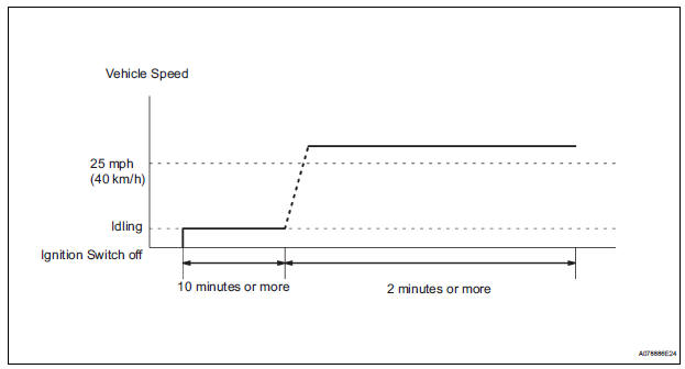
(b) Drive Pattern
(1) Connect an intelligent tester to the DLC3.
(2) Turn the ignition switch to the ON position.
(3) Clear the DTCs.
(4) Start the engine.
(5) Allow the engine to idle for 10 minutes or more.
(6) Drive the vehicle at 25 mph (40 km/h) or more for at least 2 minutes.
(c) Monitor Status
(1) Check the Readiness Monitor status displayed on the tester or scan tool.
If the status does not switch to COMPL (complete), make sure that the preconditions have been met, and repeat the Drive Pattern.
 A/F sensor and ho2s monitors
(a) Preconditions
The monitor will not run unless:
2 minutes or more have elapsed since the engine
was started.
The Engine Coolant Temperature (ECT) is 75°C
(167°F) or more.
Cumulative ...
 Problem symptoms table
HINT:
When a malfunction is not confirmed by a DTC (Diagnostic
Trouble Code) check and the cause of problem cannot be
identified through a basic inspection, troubleshoot according
to the priority ...
Other materials:
Front No. 2 speaker
COMPONENTS
ON-VEHICLE INSPECTION
1. INSPECT FRONT NO.2 SPEAKER
HINT:
Remove interior parts so that the front No.2 speaker can
be seen.
Check the speaker installation.
OK:
The speaker is securely installed.
If the result is not as specified, reinstall the front
No.2 speak ...
Starter Relay Circuit High
MONITOR DESCRIPTION
While the engine is being cranked, the positive battery voltage is applied to
terminal STA of the ECM.
If the ECM detects the Starter Control (STA) signal while the vehicle is being
driven, it determines that
there is a malfunction in the STA circuit. The ECM then il ...
Canceling the power back door system (vehicles with power
back door)
Turn the main switch off to disable
the power back door system.
Off
On*
*: The orange line at the top of the
switch indicates that the power
back door system is on.
Luggage compartment light
The luggage compartment light turns on
when the back door is opened with the
luggage ...
