Toyota Sienna Service Manual: ABS Warning Light Remains ON
DESCRIPTION
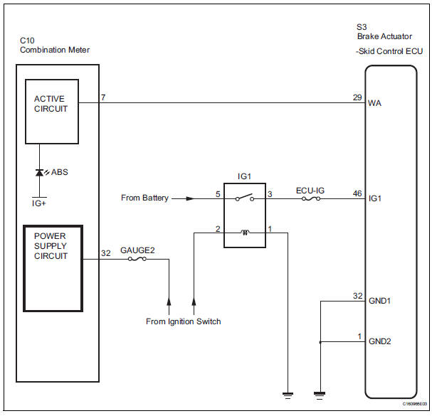
If any of the following is detected, the ABS warning light remains on.
- The skid control ECU connectors are disconnected from the skid control ECU.
- There is a malfunction in the skid control ECU internal circuit.
- There is an open in the harness between the combination meter and the skid control ECU.
HINT: In some cases, the intelligent tester cannot be used when the skid control ECU is abnormal.
WIRING DIAGRAM
INSPECTION PROCEDURE
1 CHECK DTC
(a) Is DTC output for ABS?
Result 

2 CHECK IF SKID CONTROL ECU CONNECTOR IS SECURELY CONNECTED
(a) Check the ECU connector's connecting condition.
OK: The connector should be securely connected.

3 CHECK BATTERY
(a) Check the battery voltage.
Standard voltage: 11 to 14 V

4 INSPECT SKID CONTROL ECU (IG1 TERMINAL)
(a) WHEN USING INTELLIGENT TESTER: (1) Connect the intelligent tester to the DLC3.
(2) Start the engine.
(3) Select the DATA LIST mode on the intelligent tester.
ABS / VSC: 
(4) Read the voltage condition output from the ECU displayed on the intelligent tester.
OK: "Normal" is displayed.
(b) WHEN NOT USING INTELLIGENT TESTER:
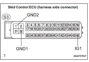
(1) Disconnect the skid control ECU connector.
(2) Turn the ignition switch to the ON position.
(3) Measure the voltage according to the value(s) in the table below.
Standard voltage 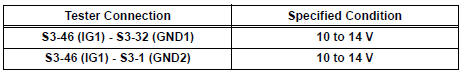


5 CHECK ABS WARNING LIGHT
(a) WHEN USING INTELLIGENT TESTER: (1) Connect the intelligent tester to the DLC3 and start the engine.
(2) Select the item "ABS WARN LIGHT" in the ACTIVE TEST and operate the ABS warning light on the intelligent tester.
(3) Check that "ON" and "OFF" of the ABS warning light can be shown on the combination meter by the intelligent tester.
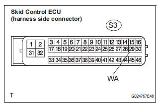
(b) WHEN NOT USING INTELLIGENT TESTER: (1) Turn the ignition switch off and disconnect the connector from the skid control ECU.
(2) Ground the terminal WA of the skid control ECU.
(3) Turn the ignition switch to the ON position.
(4) Check that the ABS warning light goes off.

REPLACE BRAKE ACTUATOR ASSEMBLY
6 CHECK HARNESS AND CONNECTOR (SKID CONTROL ECU - BODY GROUND)
(a) Disconnect the skid control ECU connector.
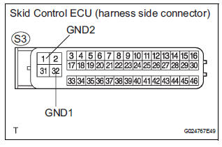
(b) Measure the resistance according to the value(s) in the table below.
Standard resistance 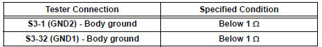
NOTICE: When replacing brake actuator assembly, perform zero point calibration (See page BC-70).

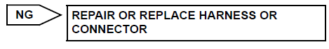
REPLACE BRAKE ACTUATOR ASSEMBLY
 Steering Angle Sensor Zero Point Malfunction
DTC C1290/66 Steering Angle Sensor Zero Point Malfunction
DESCRIPTION
The skid control ECU acquires steering angle sensor zero point every time the
ignition switch is turned to
the ON position an ...
 ABS Warning Light does not Come ON
WIRING DIAGRAM
Refer to ABS Warning Light Remains ON (See page BC-141).
INSPECTION PROCEDURE
1 CHECK ABS WARNING LIGHT
(a) Disconnect the skid control ECU connector.
(b) Turn the ignition switc ...
Other materials:
Map Disc Read Error
DTC 58-42 Map Disc Read Error
DTC 80-42 Map Disc Read Error
DESCRIPTION
DTC No.
DTC Detection Condition
Trouble Area
58-42
Player error
Scratches or dirt on the disc
Access to an invalid address due to software error
...
Yaw Rate Sensor Communication Stop Mode
DESCRIPTION
Detection Item
Symptom
Trouble Area
Yaw Rate Sensor
Communication Stop
Mode
"Yaw rate/ Deceleration sensor" is not displayed on
the "Communication Bus Check" screen of the
intelligent tester
Applies to & ...
Throttle Actuator Control Motor Circuit
DTC P2102 Throttle Actuator Control Motor Circuit Low
DTC P2103 Throttle Actuator Control Motor Circuit High
DESCRIPTION
The throttle actuator is operated by the ECM and opens and closes the
throttle valve using gears.
The opening angle of the throttle valve is detected by the Throttle Posit ...
