Toyota Sienna Service Manual: ABS Warning Light does not Come ON
WIRING DIAGRAM
Refer to ABS Warning Light Remains ON (See page BC-141).
INSPECTION PROCEDURE
1 CHECK ABS WARNING LIGHT
(a) Disconnect the skid control ECU connector.
(b) Turn the ignition switch to the ON position.
(c) Check that the ABS warning light comes on.
OK: ABS warning light comes on.
HINT: If troubleshooting has been carried out according to the PROBLEM SYMPTOMS TABLE, refer back to the table and proceed to the next step (See page BC-79).

REPLACE BRAKE ACTUATOR ASSEMBLY
2 CHECK HARNESS AND CONNECTOR (SKID CONTROL ECU - COMBINATION METER)
(a) Turn the ignition switch off.
(b) Disconnect the combination meter connector.
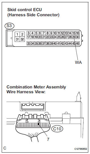
(c) Measure the resistance according to the value(s) in the table below.
Standard resistance 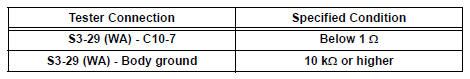

3 INSPECT COMBINATION METER ASSEMBLY
(a) Check the combination meter (See page ME-4).
HINT: If troubleshooting has been carried out according to the PROBLEM SYMPTOMS TABLE, refer back to the table and proceed to the next step (See page BC-79).

END
 ABS Warning Light Remains ON
DESCRIPTION
If any of the following is detected, the ABS warning light remains on.
The skid control ECU connectors are disconnected from the skid control
ECU.
There is a malfunction in the s ...
 VSC Warning Light Remains ON
DESCRIPTION
The skid control ECU is connected to the combination meter via CAN and
multiplex communications.
If the skid control ECU stores DTCs to shut down TRAC and VSC operation, the VSC
wa ...
Other materials:
Installation
1. INSTALL FRONT SHOULDER BELT ANCHOR
ADJUSTER ASSEMBLY
Install the front shoulder belt anchor adjuster
assembly with the bolt.
Torque: 42 N*m (430 kgf*cm, 31 ft.*lbf)
2. INSTALL CENTER PILLAR UPPER GARNISH
3. INSTALL FRONT SEAT OUTER BELT ASSEMBLY
NOTICE:
Do not disassemble ...
For vehicles equipped with catalytic converter
CAUTION: If a large amount of unburned gasoline or gasoline vapors flow
into the converter, it may cause overheating and create a fire hazard. To
prevent this, observe the following precautions:
(a) Use only unleaded gasoline.
(b) Avoid idling the engine for more than 20 minutes.
(c) ...
Typical DOT and Tire Identification Number (TIN)
DOT symbol*
Tire Identification Number (TIN)
Tire manufacturerŌĆÖs identification
mark
Tire size code
ManufacturerŌĆÖs optional tire
type code (3 or 4 letters)
Manufacturing week
Manufacturing year
*: The DOT symbol certifies that the tire conforms to applicable Federal
Mo ...
