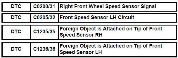
Toyota Sienna Service Manual: Right Front Wheel Speed Sensor Signal
DESCRIPTION
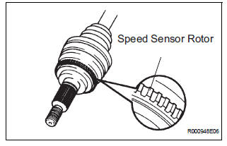
The speed sensor detects wheel speed and sends the appropriate signals to the ECU. These signals are used to control the ABS control system. The front and rear rotors have 48 serrations each.
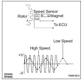
When the rotors rotate, the magnetic field emitted by the permanent magnet in the speed sensor generates AC voltage. Since the frequency of this AC voltage changes in direct proportion to the speed of the rotor, the frequency is used by the ECU to detect the speed of each wheel.
HINT:
- DTC C0200/31 and C1235/35 are for the right front speed sensor.
- DTC C0205/32 and C1236/36 are for the left front speed sensor.
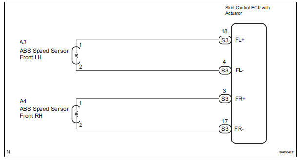
WIRING DIAGRAM
INSPECTION PROCEDURE
1 READ VALUE ON INTELLIGENT TESTER (FRONT SPEED SENSOR)
(a) Connect the intelligent tester to the DLC3.
(b) Start the engine.
(c) Select the DATA LIST mode on the intelligent tester.
ABS / VSC: 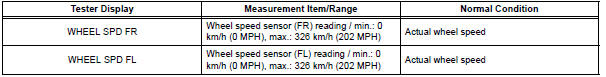
(d) Check that there is no difference between the speed value output from the speed sensor displayed on the intelligent tester and the speed value displayed on the speedometer when driving the vehicle.
OK: There is almost no difference from the displayed speed value.
HINT: There is tolerance of +- 10 % in the speedometer indication.

2 CHECK SPEED SENSOR AND SENSOR ROTOR SERRATIONS
(a) INSPECTION USING OSCILLOSCOPE
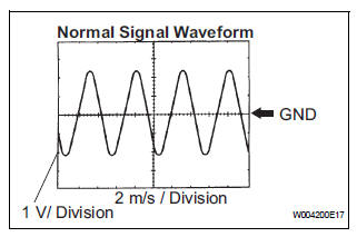
(1) Connect the oscilloscope to terminal FR+ and FRor FL+ and FL- of the skid control ECU.
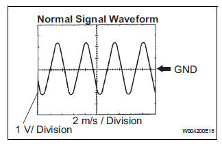
(2) Drive the vehicle at about 19 mph (30 km/h), and check the signal waveform.
OK: A waveform as shown in a figure should be output.
HINT:
- As the vehicle speed (wheel revolution speed) increases, a cycle of the waveform narrows and the fluctuation in the output voltage becomes greater.
- When noise is identified in the waveform on the oscilloscope, error signals are generated due to the speed sensor rotor's scratches, looseness or foreign matter attached to it.
NOTICE: When replacing the brake actuator assembly, perform zero point calibration (See page BC-70).

REPLACE BRAKE ACTUATOR ASSEMBLY
3 INSPECT FRONT SPEED SENSOR
(a) Make sure that there is no looseness at the connectors' locking part and connecting part of connector.
(b) Disconnect the speed sensor connector.
(c) Measure the resistance according to the value(s) in the table below.
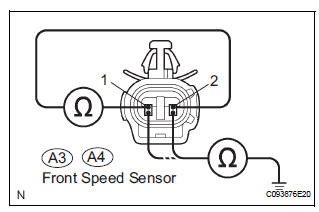
Standard resistance:
LH
RH 
(d) Measure the resistance according to the value(s) in the table below
Standard resistance:
LH 
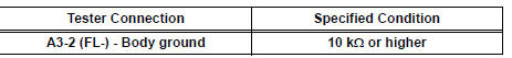
RH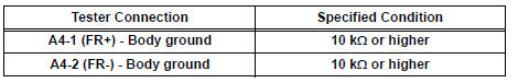
NOTICE: Check the speed sensor signal after replacement (See page BC-72).

4 CHECK HARNESS AND CONNECTOR (FRONT SPEED SENSOR - SKID CONTROL ECU)
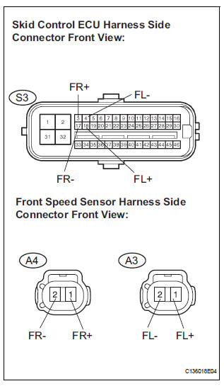
(a) Disconnect the skid control ECU connector and the front speed sensor connector.
(b) Measure the resistance according to the value(s) in the table below.
Standard resistance:
LH 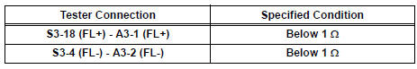
RH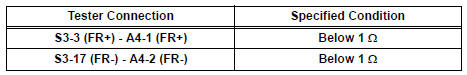
(c) Measure the resistance according to the value(s) in the table below.
Standard resistance:
LH 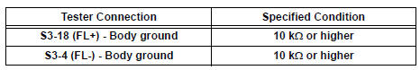
RH 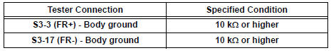

5 CHECK SPEED SENSOR AND SENSOR ROTOR SERRATIONS
(a) INSPECTION USING OSCILLOSCOPE
(1) Connect the oscilloscope to terminal FR+ and FRor FL+ and FL- of the skid control ECU.
(2) Drive the vehicle at about 19 mph (30 km/h), and check the signal waveform.
OK: A waveform as shown in a figure should be output.
HINT:
- As the vehicle speed (Wheel revolution speed) increases, a cycle of the waveform narrows and the fluctuation in the output voltage becomes greater
- When noise is identified in the waveform on the oscilloscope, error signals are generated due to the speed sensor rotor's scratches, looseness or foreign matter attached to it.
NOTICE: When replacing the brake actuator assembly, perform zero point calibration (See page BC-70).


REPLACE BRAKE ACTUATOR ASSEMBLY
6 CHECK FRONT SPEED SENSOR INSTALLATION
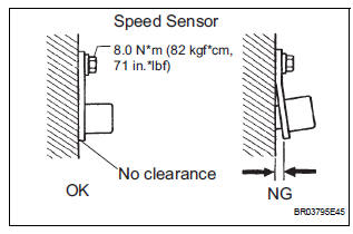
(a) Check the speed sensor installation.
OK: The installation bolt is tightened properly. There is no clearance between the sensor and the front steering knuckle.
Torque: 8.0 N*m (82 kgf*cm, 71 in.*lbf)
NOTICE: Check the speed sensor signal after the replacement (See page BC-72).

7 CHECK FRONT SPEED SENSOR TIP
(a) Remove the front speed sensor (See page BC-187).
(b) Check the sensor tip.
OK: No scratches or foreign matter on the sensor tip.
NOTICE: Check the speed sensor signal after the replacement (See page BC-72).

8 CHECK SPEED SENSOR ROTOR
(a) Remove the front drive shaft (See page DS-5).
(b) Check the sensor rotor serrations.
OK: No scratches, missing teeth or foreign matter on the rotors.
HINT: If there is foreign matter in the rotor, remove it and check the output waveform after reassembly.

REPLACE BRAKE ACTUATOR ASSEMBLY
 ABS Control System Malfunction
DTC 43 ABS Control System Malfunction
DESCRIPTION
This DTC is output when the VSC system detects a malfunction in the ABS
control system.
INSPECTION PROCEDURE
NOTICE:
When replacing the brake ...
 Right Rear Wheel Speed Sensor Signal
DESCRIPTION
Refer to DTCs C0200/31, C0205/32, C1235/35 and C1236/36 (See page BC-92).
HINT:
DTC C0210/33 and C1238/38 are for the right rear speed sensor.
DTC C0215/34 and C1239/39 are ...
Other materials:
How to proceed with
troubleshooting
1 VEHICLE BROUGHT INTO A WORKSHOP
2 DIAGNOSTIC QUESTIONING AND SYMPTOM CONFIRMATION
Ask the customer about symptoms and confirm
malfunctions.
3 CONFIRM THE SYSTEM NORMAL CONDITION
4 CHECK DTC
HINT:
If the system cannot enter the diagnosis mode, inspect each
AVC-LAN communication signal ...
Capacity and distribution
Cargo capacity depends on the total weight of the occupants.
(Cargo capacity) = (Total load capacity) - (Total weight of occupants)
Steps for Determining Correct Load Limit
Locate the statement “The combined weight of occupants and
cargo should never exceed XXX kg or XXX lbs.” on your ...
Sliding door child-protector locks
The sliding door cannot be
opened by the inside door handle
and the second seat sliding door
switch when the lock is set.
Unlock
Lock
These locks can be set to prevent
children from opening the sliding
doors. Push down on each sliding
door switch to lock that sliding
door.
The p ...
