
Toyota Sienna Service Manual: Absence of Registration Unit/ No Response for Connection Check/ Last Mode Error/ No Response Against ON / OFF Command/ Mode Status Error/ Slave Reset
DTC 01-D5 Absence of Registration Unit
DTC 01-D8 No Response for Connection Check
DTC 01-D9 Last Mode Error
DTC 01-DA No Response Against ON / OFF Command
DTC 01-DB Mode Status Error
DTC 01-DE Slave Reset
DESCRIPTION
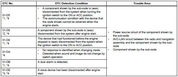
HINT:
- *1: Even if no fault is present, this trouble code may be stored depending on the battery condition or engine start voltage.
- *2: If the power connector is disconnected after the engine starts, this code is stored after 180 seconds.
- *3: This code may be stored if the engine is started and then the ignition switch is turned to the START position again.
- *4: If it is reported that the device does not exist during verification, check the power source circuit and AVC-LAN circuit for the device.
NOTICE:
- Before starting troubleshooting, be sure to clear DTCs to erase codes stored due to the reasons described in the HINT above. Then, check for DTCs and troubleshoot according to the output DTCs.
- The radio and navigation assembly is the master unit.
- Be sure to clear and recheck DTCs after the inspection is completed to confirm that no DTCs are output.
INSPECTION PROCEDURE
NOTICE: Be sure to read DESCRIPTION before performing the following procedures.
1 CHECK "RADIO AND NAVIGATION ASSEMBLY COMMUNICATION ERROR" IN FLOW CHART
Refer to the radio and navigation assembly communication error
END
 ROM Error/ RAM Error
DTC 01-21 ROM Error
DTC 01-22 RAM Error
DESCRIPTION
INSPECTION PROCEDURE
HINT:
After the inspection is completed, clear the DTCs.
1 REPLACE RADIO AND NAVIGATION ASSEMBLY
END ...
 No Master/ Connection Check Error
DTC 01-D6 No Master
DTC 01-D7 Connection Check Error
DESCRIPTION
DTC No.
DTC Detection Condition
Trouble Area
01-D6
*1
When either of the following condition ...
Other materials:
Camshaft Position Sensor
DTC P0365 Camshaft Position Sensor "B" Circuit (Bank 1)
DTC P0367 Camshaft Position Sensor "B" Circuit Low
Input (Bank 1)
DTC P0368 Camshaft Position Sensor "B" Circuit High
Input (Bank 1)
DTC P0390 Camshaft Position Sensor "B" Circuit (Bank 2)
DTC P0392 ...
Installation
1. Install purge vsv
(A) install the purge vsv with the bolt.
Torque: 10 n*m (102 kgf*cm, 7 ft.*Lbf)
(B) connect the 2 vacuum hoses and no. 1 Vacuum
switching valve connector.
2. INSTALL V-BANK COVER SUB-ASSEMBLY (See
page EM-63)
3. CONNECT CABLE TO NEGATIVE BATTERY
TERMINAL ...
How to proceed with
troubleshooting
1 VEHICLE BROUGHT TO WORKSHOP
2 CUSTOMER PROBLEM ANALYSIS
3 CHECK INITIAL CHECK FUNCTION
4 PROBLEM SYMPTOMS TABLE
THE CORRESPONDING SYSTEM DOES NOT EXIST (Go to step 5)
5 BASED ON THE MALFUNCTION SYMPTOM, PERFORM THE TROUBLESHOOTING
BELOW
Operation check (C).
Terminals of ECU
6 ...
