Toyota Sienna Service Manual: Installation
1. Install purge vsv
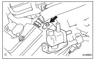
(A) install the purge vsv with the bolt.
Torque: 10 n*m (102 kgf*cm, 7 ft.*Lbf)
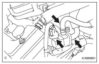
(B) connect the 2 vacuum hoses and no. 1 Vacuum switching valve connector.
2. INSTALL V-BANK COVER SUB-ASSEMBLY (See page EM-63) 3. CONNECT CABLE TO NEGATIVE BATTERY TERMINAL
 Inspection
1. INSPECT PURGE VSV
(a) Measure the resistance of the purge VSV.
Standard resistance
If the result is not as specified, replace the purge
VSV.
(b) Check the operation of the purge VSV. ...
 Ventilation valve
Components
...
Other materials:
Mass or Volume Air Flow Circuit
DESCRIPTION
The Mass Air Flow (MAF) meter is a sensor that measures the amount of air
flowing through the throttle
valve. The ECM uses this information to determine the fuel injection time and to
provide appropriate airfuel
ratio. Inside the MAF meter, there is a heated platinum wire whic ...
How to proceed with
troubleshooting
HINT:
*: Use the intelligent tester.
1 VEHICLE BROUGHT TO WORKSHOP
2 CUSTOMER PROBLEM ANALYSIS
Confirm problem symptoms
3 CHECK MULTIPLEX COMMUNICATION SYSTEM*
Check if the multiplex communication system DTC is
output.
HINT:
The center airbag sensor assembly of this system is
co ...
Sound Signal Circuit between Radio Receiver and Television Display
Assembly
DESCRIPTION
The television display assembly sends a sound signal to the radio receiver
through this circuit.
The sound signal that has been sent is amplified by the stereo component
amplifier or radio receiver
(built-in amplifier), and then is sent to the speakers.
If there is an open or ...
