Toyota Sienna Service Manual: Adjustment
HINT: If the malfunction does not disappear by following the procedure in ADJUSTMENT and the rear No. 2 seat assembly needs to be replaced, do not disassemble the rear No. 2 seat assembly.
1. ADJUST FRONT LEG
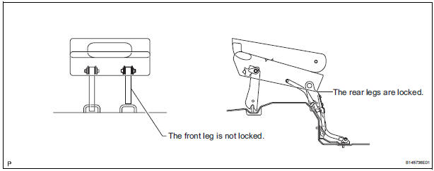
HINT: Perform the following procedure if the inner leg does not lock.
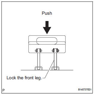
- Push down on the rear No. 2 seat assembly to lock the front leg.
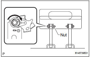
- Loosen the bolt on the front leg that has locked and move the rear No. 2 seat assembly up and down a few times.
NOTICE: Check that the front leg plate moves.

- Tighten the bolt.
Torque: 14.5 N*m (153 kgf*cm, 11 ft.*lbf) NOTICE: Hold the nut to prevent it from turning.
- Check that the rear No. 2 seat assembly operates
normally and both front legs lock securely.
NOTICE: If any of the front legs do not lock, loosen the bolt on the front leg that has not locked, and perform the procedure from (b) again.
2. REINSTALL REAR NO. 2 SEAT ASSEMBLY
HINT: Perform the following procedure if the rear No. 2 seat assembly is removed with any of the 4 legs released or if the rear legs are moved with the rear No. 2 seat assembly removed.
- Remove the following components:
- Rear No. 2 seat leg side garnish sub-assembly
- Rear seat leg garnish sub-assembly
- No. 2 seat hinge cover
- Rear No. 2 seat assembly
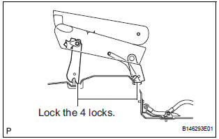
- Lock the rear legs to the striker.
- Lock the front legs to the striker.
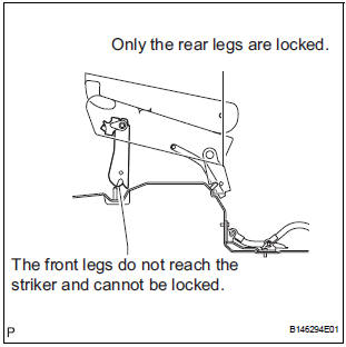
- If any of the front legs do not lock, perform the following procedure:
- Connect the connector.
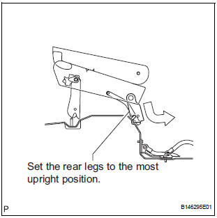
- Operate the stowing/return switch to set the rear legs to the most upright position.
- Lock the front legs to the striker.

- Align the links of the No. 2 seat leg sub-assembly with the No. 2 seat cushion frame sub-assembly.
- Align the screw holes on the No. 2 cushion frame
sub-assembly with the square link holes on the No.
2 seat leg sub-assembly.
HINT: If the holes do not align, move the No. 2 seat cushion frame sub-assembly horizontally to align the holes.

- Operate the stowing/return switch to adjust the rear legs so that the rear legs fit to the links of the No. 2 seat leg sub-assembly as shown in the illustration.

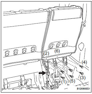
- Install the 6 bolts.
Torque: 19 N*m (194 kgf*cm, 14 ft.*lbf) NOTICE: Tighten the bolts in the order shown in the illustration.
- Install the following components:
- No. 2 seat hinge cover
- Rear seat leg garnish sub-assembly
- Rear No. 2 seat leg side garnish sub-assembly
- Check that the rear No. 2 seat assembly operates normally and the rear legs lock securely.
NOTICE: If any of the front legs do not lock normally, perform the procedure in "1. ADJUST FRONT LEG".
 Disassembly
1. REMOVE REAR NO. 2 SEAT COVER BEZEL
Remove the 3 screws.
Disengage the 3 claws and remove the rear No. 2
seat cover bezel.
2. REMOVE REAR SEAT RECLINING COVER RH
& ...
 Reassembly
1. INSTALL NO. 2 SEAT LEG SUB-ASSEMBLY
Install the No. 2 seat leg sub-assembly with the 3
bolts and nut.
Torque: 19 N*m (194 kgf*cm, 14 ft.*lbf)
NOTICE:
Tighten the bolts and nut ...
Other materials:
Installation
1. INSTALL CRANKSHAFT POSITION SENSOR
Apply a light coat of engine oil to the O-ring on the
crankshaft position sensor.
Install the crankshaft position sensor with the bolt.
Torque: 9.0 N*m (92 kgf*cm, 80 in.*lbf)
Connect the crankshaft position sensor connector.
...
Open in One Side of CAN Branch Line
DESCRIPTION
If 2 or more ECUs and/or sensors do not appear on the intelligent tester
"Communication Bus Check"
screen, one side of the CAN branch wire may be open. (One side of the CAN-H
[branch wire] / CAN-L
[branch wire] of the ECU and/or sensor is open.)
Symptom
...
Fuel Receiver Gauge Malfunction
DESCRIPTION
The meter CPU uses the fuel sender gauge assembly to determine the level of
the fuel in the fuel tank.
The resistance of the fuel sender gauge will vary between approximately 15 Ω
with the float at the full
position, and 410 Ω with the float at the empty position. The ...
