Toyota Sienna Service Manual: Disassembly
HINT: On the RH side, use the same procedures as on the LH side.
1. REMOVE REAR DOOR WINDOW FRAME MOULDING REAR LH (See page ET-30)
2. REMOVE REAR DOOR WINDOW FRAME MOULDING SUB-ASSEMBLY LH (See page ET-21)
3. REMOVE SLIDE DOOR WINDOW GARNISH LH
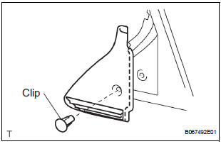
- Fully open the slide door window.
- Remove the glass run.
- Using a screwdriver, disengage the clip and remove
the garnish.
HINT: Tape the screwdriver tip before use.
- Using a screwdriver, disengage the 2 claws and
remove the weatherstrip inner from the garnish.
HINT: Tape the screwdriver tip before use.
4. REMOVE SIDE TRIM BOARD COVER REAR LH
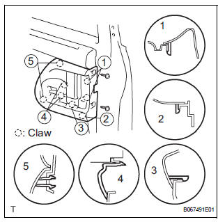
- Remove the 2 screws.
- Using a screwdriver, disengage the 8 claws and
remove the cover together with the window control
switch.
HINT: Tape the screwdriver tip before use.
- Remove the 2 screws and window control switch.
5. REMOVE REAR DOOR TRIM BOARD SUBASSEMBLY LH
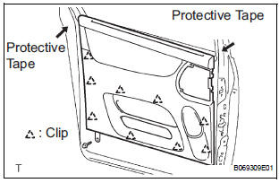
- Remove the screw.
- Using a screwdriver, disengage the 9 clips and remove the trim board.
HINT:
- Tape the screwdriver tip before use.
- In order to prevent the door panel from being damaged, cover the areas with protective tape as indicated by arrow marks in the illustration.
- Using a clip remover, remove the 6 clips and weatherstrip No. 2.
- Using a screwdriver, disengage the 11 claws and remove the weatherstrip inner from trim board.
HINT: Tape the screwdriver tip before use.

- w/ Sunshade: Remove the sunshade.
- Remove the 7 screws and sunshade bezel.
- Remove the 4 screws and curtain.
6. REMOVE SLIDE DOOR WINDOW ASSEMBLY LH
- w/ Sunshade: Remove the sunshade hook.
- Remove the bolt and window frame.
- Remove the bolt.
- Loosen the nut.
- Push the window frame rear lower in the direction indicated by the arrow mark in the illustration.
- Remove the 2 hole plugs.
- Move the window until the bolts appear in the service holes.
NOTICE:
- Do not damage the window assembly.
- When the bolts are removed, the window assembly may fall and become deformed.
- Remove the 2 bolts and window.
7. REMOVE REAR DOOR GLASS WEATHERSTRIP ASSEMBLY OUTER LH
8. REMOVE SLIDE DOOR ATTACHMENT CONTROL LH
- Remove the 2 screws, bolt and inside handle.
- Disconnect the connectors from the lock actuator and power window regulator motor.
- Disengage the control cables.
- Remove the 8 bolts and attachment control.
- Remove the nut and the window frame rear lower.
NOTICE: When the nut is removed, the window frame may fall and become deformed.
HINT: Remove the window frame rear lower through the service hole.
- Remove the control rod.
- Remove the 3 bolts and lock remote control.
- Remove the 2 screws and lock actuator
- Remove the 3 screws and power window regulator motor.
- Remove the half stop control lever and door lock control bellcrank.
- Remove the 4 bolts and window regulator.
9. REMOVE REAR DOOR STIFFENER CUSHION LH
- Remove 2 hole plugs.
- Remove the 2 screws, clip and stiffener cushion.
HINT: Remove the stiffener cushion through the service hole.
- Remove the 2 grommets and 2 clips.
10. REMOVE REAR DOOR OUTSIDE HANDLE COVER LH
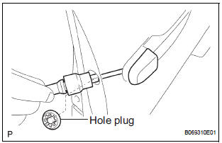
- Remove the hole plug.
- Using a torx socket wrench (T30), loosen the screw and remove the outside handle cover with the lock key cylinder installed.
11. REMOVE REAR DOOR OUTSIDE HANDLE ASSEMBLY LH
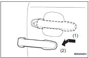
- Pushing and pulling the outside handle in the direction indicated by the arrow mark in the illustration, remove the outside handle.
- Remove the outside handle pads front and rear.
12. REMOVE REAR DOOR OUTSIDE HANDLE FRAME SUB-ASSEMBLY LH
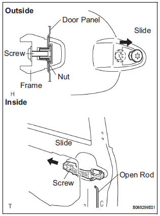
- Remove the open rod to the outside handle frame.
- Using a torx socket wrench (T30), loosen the screw.
- Slide the outside handle frame in the direction indicated by the arrow mark in the illustration and remove it.
HINT: Remove the outside handle frame through the service hole.
13. REMOVE SLIDE DOOR LOCK ASSEMBLY FRONT LH
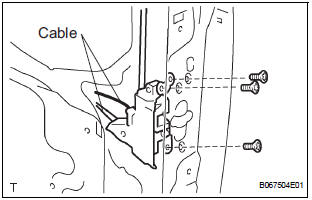
- Remove the 2 cables.
- Using a torx socket wrench (T30), remove the 3 screws and lock.
HINT: Remove the lock through the service hole.
14. REMOVE REAR DOOR LOCK ASSEMBLY LH
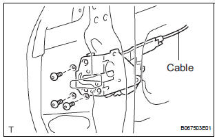
- Remove the cable.
- Using the torx socket wrench (T30), remove the 3 screws and lock.
HINT: Remove the lock through the service hole.
15. REMOVE REAR DOOR WIRE SUB-ASSEMBLY LH
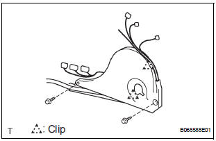
- Remove the 2 screws.
- Using a screwdriver, remove the 2 clips and door wire.
HINT: Tape the screwdriver tip before use.
 Removal
HINT:
On the RH side, use the same procedures as on the LH side.
1. REMOVE SLIDE DOOR
Remove the rear door scuff plate (See page IR-7).
Remove the back door scuff plate (See page ED-
214 ...
 Adjustment
HINT:
On the RH side, use the same procedures as on the LH side.
1. INSPECT SLIDE DOOR PANEL SUB-ASSEMBLY LH
Check that the clearance is within the standard
range.
Standard
2. ADJU ...
Other materials:
Approach warning
When your vehicle is too close to a vehicle ahead, and sufficient automatic
deceleration via the cruise control is not possible, the display
will flash and the buzzer will sound to alert the driver. An example of
this would be if another driver cuts in front of you while you are following
a vehi ...
How to use this manual
GENERAL INFORMATION
1. GENERAL DESCRIPTION
(a) This manual is written in accordance with SAE J2008.
(b) Repair operations can be separated mainly in the following 3 processes:
(1) Diagnosis
(2) Removing / Install ...
Installation
1. INSTALL AMPLIFIER ANTENNA ASSEMBLY
Engage the 16 clamps to install the amplifier
antenna assembly.
Install the 3 bolts.
Connect the connectors.
2. INSTALL ROOF HEADLINING ASSEMBLY
3. INSTALL ANTENNA ASSEMBLY WITH HOLDER
Install the antenna assembly ...
