Toyota Sienna Service Manual: Reassembly
1. INSTALL REAR DOOR WIRE SUB-ASSEMBLY LH
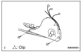
- Install the wire.
NOTICE: When installing the wire, push the areas where the clips are installed in order to prevent damage and deformation.
- Install the 2 screws.
2. INSTALL REAR DOOR LOCK ASSEMBLY LH
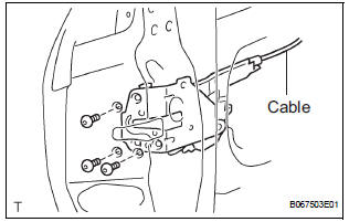
- Apply MP grease to the sliding and rotating areas of the lock.
- Apply adhesive to the threads of the screws.
Adhesive: Part No. 08833-00070, THREE BOND 1324 or equivalent
- Install the lock to the door panel with the 3 screws.
Torque: 5.0 N*m (51 kgf*cm, 44 in.*lbf)
- Connect the cable.
3. INSTALL SLIDE DOOR LOCK ASSEMBLY FRONT LH
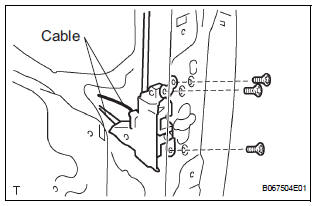
- Apply MP grease to the sliding and rotating areas of the lock.
- Apply adhesive to the threads of the screws.
Adhesive: Part No. 08833-00070, THREE BOND 1324 or equivalent
- Install the lock front to the door panel with the 3
screws.
Torque: 5.0 N*m (51 kgf*cm, 44 in.*lbf)
- Connect the 2 cables.
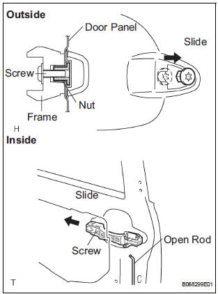
4. INSTALL REAR DOOR OUTSIDE HANDLE FRAME SUB-ASSEMBLY LH
- Apply MP grease to the sliding and rotating parts of the outside handle frame.
- Slide the outside handle frame in the direction indicated by the arrow mark in the illustration.
- Using a torx socket wrench (T30), install the outside
handle frame with the screw.
Torque: 7.0 N*m (71 kgf*cm, 62 in.*lbf) NOTICE: Insert a cover between the nut and the door panel.
- Install the open rod.
 Adjustment
HINT:
On the RH side, use the same procedures as on the LH side.
1. INSPECT SLIDE DOOR PANEL SUB-ASSEMBLY LH
Check that the clearance is within the standard
range.
Standard
2. ADJU ...
 Reassembly
1. INSTALL REAR DOOR WIRE SUB-ASSEMBLY LH
Install the wire.
NOTICE:
When installing the wire, push the areas where
the clips are installed in order to prevent
damage and deformation.
...
Other materials:
Adjustment
1. INSPECT SHIFT LEVER POSITION
(a) When shifting from P to R position only with ignition
switch ON and brake pedal, make sure that the
shifting lever moves smoothly and can be
moderately operated.
(b) When starting engine, make sure that the vehicle
moves forward when shifting from N to D p ...
Wrong Disc/ Disc cannot be Read
DTC 44-41 Wrong Disc
DTC 44-42 Disc cannot be Read
DESCRIPTION
DTC No.
DTC Detecting Condition
Trouble Area
44-41
An unsuitable disc is inserted
DVD
Television display assembly
44-42
The disc cannot be read.
IN ...
Short to GND in Front Passenger Side Squib
2nd Step Circuit
DTC B1187/55 Short to GND in Front Passenger Side Squib
2nd Step Circuit
DESCRIPTION
The front passenger side squib 2nd step circuit consists of the center airbag
sensor assembly and the
front passenger airbag assembly.
The circuit instructs the SRS to deploy when deployment conditions are ...
