Toyota Sienna Service Manual: Air Inlet Damper Control Servo Motor Circuit
DESCRIPTION
The air inlet control servo motor is controlled by the A/C amplifier and moved to the desired position.
The air inlet control servo motor switches the air inlet mode by rotating
(normal, reverse) with electrical
power from the A/C amplifier. This controls intake air and changes the mode
between
"RECIRCULATION", "FRESH", and "HALF-RECIRCULATION".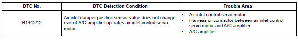
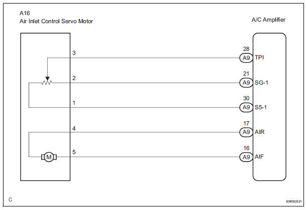
WIRING DIAGRAM
INSPECTION PROCEDURE
1 READ VALUE OF INTELLIGENT TESTER
(a) Connect the intelligent tester to the DLC3.
(b) Turn the ignition switch to the ON position and turn the intelligent tester main switch on.
(c) Select the items below in the DATA LIST, and read the display on the intelligent tester.
DATA LIST / AIR CONDITIONER 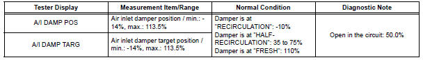
OK: When the target position is "RECIRCULATION" (- 10%), the actual opening angle is 19.0% or less.
When the target position is "FRESH" (110%), the actual opening angle is 81.0% or more.
Result 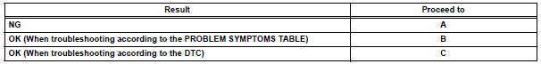

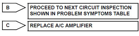
2 PERFORM ACTIVE TEST BY INTELLIGENT TESTER
(a) Remove the glove box to see and check the recirculation damper operation.
(b) Connect the intelligent tester to the DLC3.
(c) Turn the ignition switch to the ON position and turn the intelligent tester main switch on.
(d) Select the item below in the ACTIVE TEST and then check that the damper operates.
ACTIVE TEST / AIR CONDITIONER 
OK: Lever turns from "RECIRCULATION" side to "FRESH" side smoothly.
Lever turns from "FRESH" side to "RECIRCULATION" side smoothly.
Result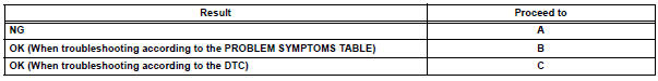

3 PERFORM ACTUATOR CHECK
(a) Remove the glove box to see and check the recirculation damper operation.
(b) Enter the actuator check mode (See page AC-15).
(c) Press the DEF switch and check the operation of the
recirculation damper.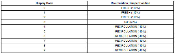
OK: Recirculation damper position changes in accordance with each display code.
Result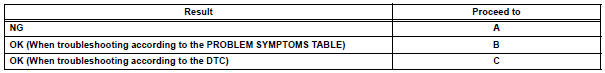

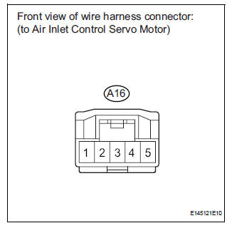
4 INSPECT AIR INLET CONTROL SERVO MOTOR
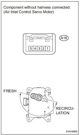
(a) Remove the air inlet control servo motor.
(b) Disconnect the connector from the air inlet control servo motor.
(c) Connect the positive (+) lead from the battery to terminal 5 and the negative (-) lead to terminal 4, then check that the lever turns to the "FRESH" position smoothly.
OK: Lever turns to "FRESH" position smoothly.
(d) Connect the positive (+) lead from the battery to terminal 4 and the negative (-) lead to terminal 5, then check that the lever turns to the "RECIRCULATION" position smoothly.
OK: Lever turns to "RECIRCULATION" position smoothly.

5 CHECK HARNESS AND CONNECTOR (AIR INLET CONTROL SERVO MOTOR - A/C AMPLIFIER)
(a) Disconnect the connector from the A/C amplifier.
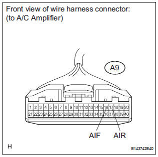
(b) Measure the resistance according to the value(s) in the table below.
Standard resistance 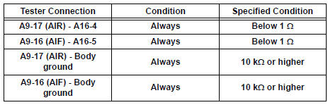

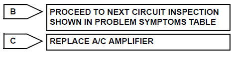
REPLACE A/C AMPLIFIER
 Air Mix Damper Control Servo Motor Circuit (Passenger Side)
DESCRIPTION
The air mix control servo motor (air mix damper servo sub-assembly) is
controlled by the A/C amplifier.
The air mix control servo motor moves the air mix damper by rotating (normal, ...
 Air Outlet Damper Control Servo Motor Circuit
DESCRIPTION
This circuit turns the servo motor and changes each damper position by
receiving the signals from the A/
C amplifier.
The air outlet damper servo motor switches the air outlet mode ...
Other materials:
Confirmation of transmitter id registration
(a) Make sure that the ignition switch is off.
(b) Connect the intelligent tester to DLC3.
(c) Turn the ignition switch to the ON position.
(d) Select "TIREPRESS" by following the prompts
displayed on the intelligent tester.
(e) Confirm that the data of tire pressure of all ti ...
Inspection
1. INSPECT UNDERDRIVE PLANETARY GEAR PRELOAD
(a) Using SST, fix the underdrive planetary gear
assembly.
SST 09387-00050
(b) Using SST and a torque wrench, measure the
turning torque of the underdrive planetary gear
assembly while rotating the torque wrench at 60
rpm.
SST 09387-00050
...
Throttle / Pedal Position Sensor
HINT:
These DTCs relate to the Accelerator Pedal Position (APP) sensor.
DESCRIPTION
HINT:
This ETCS (Electronic Throttle Control System) does not use a throttle cable.
The Accelerator Pedal Position (APP) sensor is integrated with the accelerator
pedal bracket and has 2
sensor circuits ...
