Toyota Sienna Service Manual: Camshaft Position Sensor "A" Circuit
DTC P0340 Camshaft Position Sensor "A" Circuit (Bank 1 or Single Sensor)
DTC P0342 Camshaft Position Sensor "A" Circuit Low Input (Bank 1 or Single Sensor)
DTC P0343 Camshaft Position Sensor "A" Circuit High Input (Bank 1 or Single Sensor)
DTC P0345 Camshaft Position Sensor "A" Circuit (Bank 2)
DTC P0347 Camshaft Position Sensor "A" Circuit Low Input (Bank 2)
DTC P0348 Camshaft Position Sensor "A" Circuit High Input (Bank 2)
DESCRIPTION
The intake camshaft's Variable Valve Timing (VVT) sensor (G signal) consists of a magnet and MRE (Magneto Resistance Element).
The VVT camshaft drive gear has a sensor plate with 3 teeth on its outer circumference. When the gear rotates, changes occur in the air gaps between the sensor plate and MRE, which affects the magnetic field. As a result, the resistance of the MRE material fluctuates. The VVT sensor converts the gear rotation data to pulse signals, uses the pulse signals to determine the camshaft angle, and sends it to the ECM.
The crankshaft angle sensor plate has 34 teeth. The pickup coil generates 34 signals for each engine revolution. Based on combination of the G signal and NE signal, the ECM detects the crankshaft angle.
Then the ECM uses this data to control fuel injection time and injection timing. Also, based on the NE signal, the ECM detects the engine speed.
|
DTC No. |
DTC Detection Condition |
Trouble Area |
| P0340 P0345 |
|
|
| P0342 P0347 |
Output voltage of VVT sensor is 0.3 V or less for 5 seconds (1 trip detection logic) |
|
| P0343 P0348 |
Output voltage of VVT sensor is 4.7 V or more for 5 seconds (1 trip detection logic) |
|
Reference: Inspection using an oscilloscope
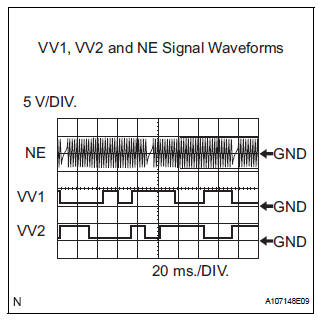
HINT:
- The correct waveform is shown in the illustration.
- VV1+ and VV2+ stand for the VVT sensor signal, and NE+ stands for the CKP sensor signal.

MONITOR DESCRIPTION
If no signal is transmitted by the VVT sensor despite the engine revolving, or the rotations of the camshaft and the crankshaft are not synchronized, the ECM interprets this as a malfunction of the sensor.
MONITOR STRATEGY
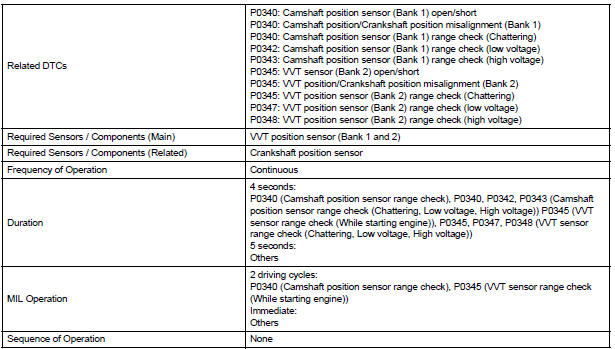
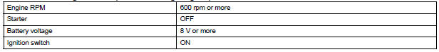
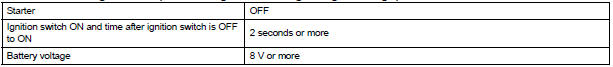
TYPICAL ENABLING CONDITIONS
All:

Camshaft Position Sensor Range Check:

Camshaft Position/Crankshaft Position Misalignment:

Camshaft Position Sensor Range Check (Chattering, Low voltage, High voltage):

VVT sensor range check (While starting engine):

VVT sensor range check (After starting engine):
VVT sensor range check (Chattering, Low voltage, High voltage):
TYPICAL MALFUNCTION THRESHOLDS
Camshaft Position Sensor Range Check:

Camshaft Position/Crankshaft Position Misalignment:

Camshaft Position Sensor Range Check (Fluctuating):

Camshaft Position Sensor Range Check (Low voltage):

Camshaft Position Sensor Range Check (High voltage):

VVT sensor range check (While starting engine):

VVT sensor range check (After starting engine):

VVT sensor range check (Fluctuating):

VVT sensor range check (Low voltage):

VVT sensor range check (High voltage):

COMPONENT OPERATING RANGE

WIRING DIAGRAM
Refer to DTC P0335.
INSPECTION PROCEDURE
HINT: Read freeze frame data using the intelligent tester. The ECM records vehicle and driving condition information as freeze frame data the moment a DTC is stored. When troubleshooting, freeze frame data can be helpful in determining whether the vehicle was running or stopped, whether the engine was warmed up or not, whether the air-fuel ratio was lean or rich, as well as other data recorded at the time of a malfunction.
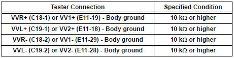
1 CHECK HARNESS AND CONNECTOR (SENSOR POWER SOURCE)
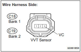
- Disconnect the C18 or C19 VVT sensor connector.
- Measure the voltage according to the value(s) in the table below.
Standard voltage
- Reconnect the VVT sensor connector.
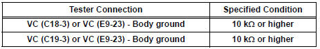
2 CHECK HARNESS AND CONNECTOR (VVT SENSOR - ECM)
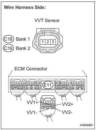
- Disconnect the C18 or C19 VVT sensor connector.
- Disconnect the E11 ECM connector.
- Measure the resistance according to the value(s) in the table below.
Standard resistance : Check for open
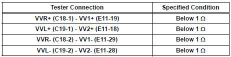
Check for short
- Reconnect the VVT sensor connector.
- Reconnect the ECM connector.
3 CHECK SENSOR INSTALLATION (VVT SENSOR)
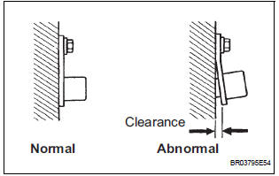
- Check the VVT sensor installation condition.
OK: Sensor is installed correctly.
4 CHECK CAMSHAFT TIMING GEAR ASSEMBLY (TEETH OF PLATE)
- Check the teeth of the signal plate.
OK: Sensor plate teeth do not have any cracks or deformation.
5 REPLACE VVT SENSOR
- Replace the VVT sensor
6 CHECK WHETHER DTC OUTPUT RECURS
- Connect the intelligent tester to the DLC3.
- Turn the ignition switch to the ON position.
- Turn the intelligent tester on.
- Clear the DTCs.
- Select the following menu items: DIAGNOSIS / ENHANCED OBD II / DTC / INFO / PENDING CODES.
- Read the DTCs
Result

HINT: If the engine does not start, replace the ECM.
END
7 CHECK HARNESS AND CONNECTOR (VVT SENSOR - ECM)
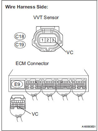
- Disconnect the C18 or C19 VVT sensor connector.
- Disconnect the E9 ECM connector.
- Measure the resistance according to the value(s) in the table below.
Standard resistance : Check for open
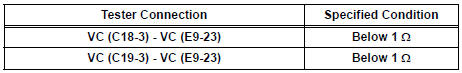
Check for short
- Reconnect the VVT sensor connector.
- Reconnect the ECM connector
REPLACE ECM
 Crankshaft Position Sensor "A" Circuit
DTC P0335 Crankshaft Position Sensor "A" Circuit
DTC P0339 Crankshaft Position Sensor "A" Circuit Intermittent
DESCRIPTION
The Crankshaft Position (CKP) sensor system consists o ...
 Ignition Coil Primary / Secondary Circuit
DTC P0351 Ignition Coil "A" Primary / Secondary Circuit
DTC P0352 Ignition Coil "B" Primary / Secondary Circuit
DTC P0353 Ignition Coil "C" Primary / Secondary Circuit
...
Other materials:
Reassembly
1. INSTALL FRONT SEAT CUSHION SHIELD LOWER LH
Install the front seat cushion shield lower LH.
2. INSTALL FRONT SEAT CUSHION SHIELD LOWER
RH
3. INSTALL RECLINING ADJUSTER INSIDE COVER LH
Install the reclining adjuster inside cover LH (upper)
with the screw.
4. INSTALL RE ...
Disc cannot be Played/ No Playable Files/ Copyright Protection Error
DTC 44-7D Disc cannot be Played
DTC 44-7E No Playable Files
DTC 44-7F Copyright Protection Error
DESCRIPTION
DTC No.
DTC Detecting Condition
Trouble Area
44-7D
An incompatible MP3/WMA file is used.
Although the file has an extension of " ...
Engine Coolant Temperature Circuit Range / Performance Problem
DESCRIPTION
Refer to DTC P0115 (See page ES-133).
MONITOR DESCRIPTION
The ECT sensor is used to monitor the ECT. The ECT sensor has a built-in
thermistor with a resistance
that varies according to the temperature of the engine coolant. When the ECT
becomes low, the
resistance of the ...
