Toyota Sienna Service Manual: Ignition Coil "A" Primary
HINT:
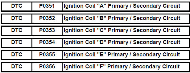
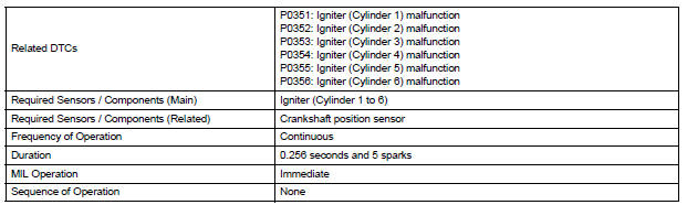
- These DTCs indicate malfunctions relating to the primary circuit.
- If DTC P0351 is set, check the No. 1 ignition coil with igniter circuit.
- If DTC P0352 is set, check the No. 2 ignition coil with igniter circuit.
- If DTC P0353 is set, check the No. 3 ignition coil with igniter circuit.
- If DTC P0354 is set, check the No. 4 ignition coil with igniter circuit.
- If DTC P0355 is set, check the No. 5 ignition coil with igniter circuit.
- If DTC P0356 is set, check the No. 6 ignition coil with igniter circuit.
DESCRIPTION
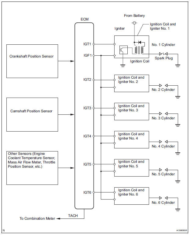
A Direct Ignition System (DIS) is used on this vehicle.
The DIS is a 1-cylinder ignition system in which each cylinder is ignited by one ignition coil and one spark plug is connected to the end of each secondary wiring. High-voltage is generated in the secondary wiring and then applied directly to each spark plug. The sparks of the spark plugs pass from the center electrodes to the ground electrodes.
The ECM determines the ignition timing and transmits the ignition (IGT) signals to each cylinder. Using the IGT signal, the ECM turns the power transistor inside the igniter on and off. The power transistor, in turn, switches on and off the current to the primary coil. When the current to the primary coil is cut off, highvoltage is generated in the secondary coil. This voltage is applied to the spark plugs, causing them to spark inside the cylinders. As the ECM cuts the current to the primary coil off, the igniter sends back an ignition confirmation (IGF) signal to the ECM, for each cylinder ignition.
Reference: Inspection using an oscilloscope
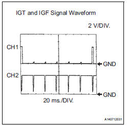
While cranking or idling, check the waveform between terminals IGT (1 to 6)
and E1, and IGF1 and E1 of
the ECM connector. 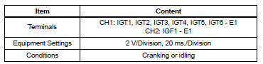
MONITOR DESCRIPTION
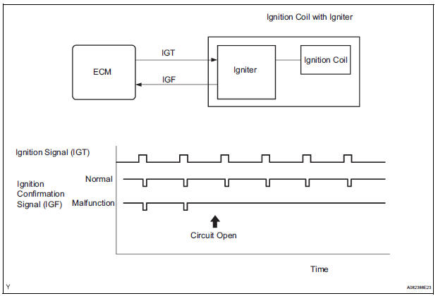
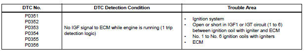
If the ECM does not receive any IGF signals despite transmitting the IGT signal, it interprets this as a fault in the igniter and sets a DTC.
If the malfunction is not repaired successfully, a DTC is set 1 second after the engine is next started.
MONITOR STRATEGY
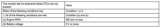
TYPICAL ENABLING CONDITIONS

TYPICAL MALFUNCTION THRESHOLDS

COMPONENT OPERATING RANGE

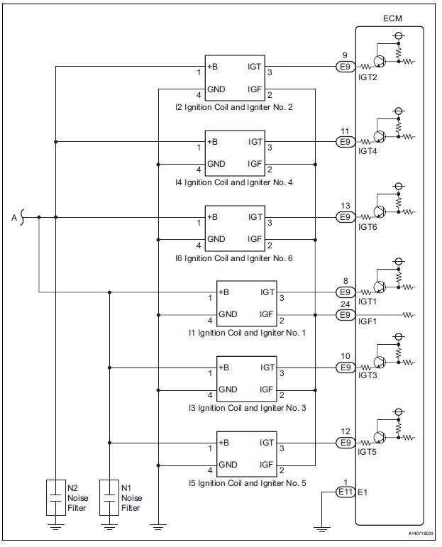
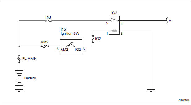
WIRING DIAGRAM
INSPECTION PROCEDURE
HINT:
Read freeze frame data using the intelligent tester. The ECM records vehicle and driving condition information as freeze frame data the moment a DTC is stored. When troubleshooting, freeze frame data can be helpful in determining whether the vehicle was running or stopped, whether the engine was warmed up or not, whether the air-fuel ratio was lean or rich, as well as other data recorded at the time of a malfunction.
1 CHECK FOR SPARKS AND CHECK SPARK PLUG OF MISFIRING CYLINDER
HINT: (See page ES-211)

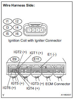
2 CHECK HARNESS AND CONNECTOR (IGNITION COIL ASSEMBLY - ECM (IGF1 SIGNAL TERMINAL))
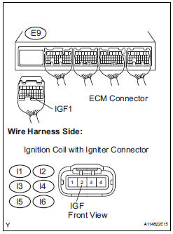
(a) Disconnect the I1, I2, I3, I4, I5 or I6 ignition coil with igniter connector.
(b) Disconnect the E9 ECM connector.
(c) Measure the resistance according to the value(s) in the table below.
Standard resistance: 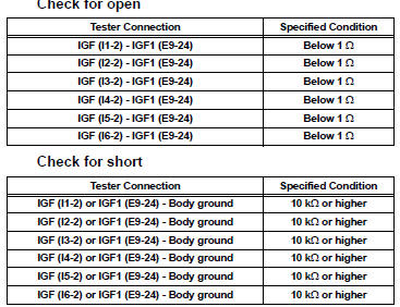
(d) Reconnect the ECM connector.
(e) Reconnect the ignition coil with igniter connector.

3 INSPECT ECM (IGF1 VOLTAGE)
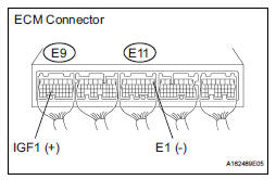
(a) Disconnect the I1, I2, I3, I4, I5 or I6 ignition coil with igniter connector.
(b) Turn the ignition switch to the ON position.
(c) Measure the voltage according to the value(s) in the table below.
Standard voltage 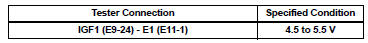
(d) Reconnect the ignition coil connector.

REPLACE IGNITION COIL ASSEMBLY (See page IG-8)
4 CHECK HARNESS AND CONNECTOR (IGNITION COIL ASSEMBLY - ECM (IGT SIGNAL TERMINAL))
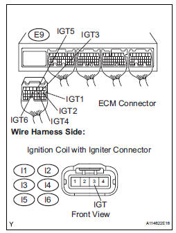
(a) Disconnect the I1, I2, I3, I4, I5 or I6 ignition coil with igniter connector.
(b) Disconnect the E9 ECM connector.
(c) Measure the resistance according to the value(s) in the table below.
Standard resistance : 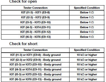

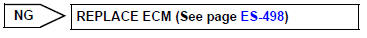
5 INSPECT ECM (IGT1, IGT2, IGT3, IGT4, IGT5 OR IGT6 VOLTAGE)
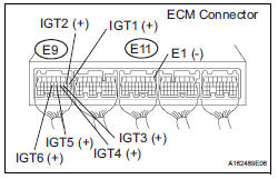
(a) Turn the ignition switch to the ON position.
(b) Measure the voltage according to the value(s) in the table below.
Standard voltage 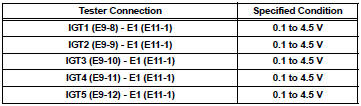
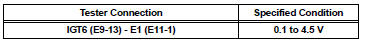

6 INSPECT ECM (IGT1, IGT2, IGT3, IGT4, IGT5 OR IGT6 VOLTAGE)
(a) Disconnect the I1, I2, I3, I4, I5 or I6 ignition coil connector.
(b) Turn the ignition switch to the ON position.
(c) Measure the voltage according to the value(s) in the table below.
Standard voltage 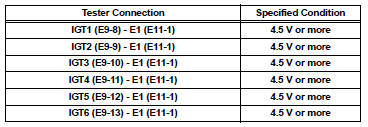
(d) Reconnect the ignition coil connector.

7 INSPECT IGNITION COIL ASSEMBLY (POWER SOURCE)
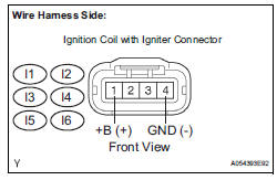
(a) Disconnect the I1, I2, I3, I4, I5 or I6 ignition coil with igniter connector.
(b) Measure the resistance according to the value(s) in the table below.
Standard resistance: 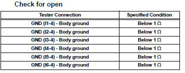
(c) Turn the ignition switch to the ON position.
(d) Measure the voltage according to the value(s) in the table below.
Standard voltage 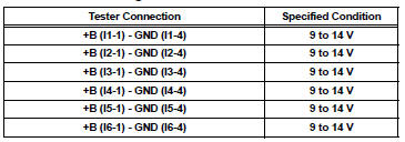
(e) Reconnect the ignition coil with igniter connector.


REPLACE IGNITION COIL ASSEMBLY (See page IG-8)
8 INSPECT RELAY (IG2 RELAY)
(a) Remove the IG2 relay from the No. 3 engine room R/B.
(b) Measure the resistance according to the value(s) in the table below.
Standard resistance 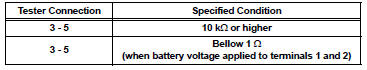
(c) Reinstall the IG2 relay.


REPAIR OR REPLACE HARNESS OR CONNECTOR (IGNITION COIL ASSEMBLY - IGNITION SWITCH)
 Camshaft Position Sensor "A" Circuit
DESCRIPTION
The intake camshaft's Variable Valve Timing (VVT) sensor (G signal) consists
of a magnet and MRE
(Magneto Resistance Element).
The VVT camshaft drive gear has a sensor plate wit ...
 Camshaft Position Sensor "B" Circuit
DESCRIPTION
The exhaust camshaft's Variable Valve Timing (VVT) sensor consists of a
magnet and MRE (Magneto
Resistance Element).
The exhaust camshaft has a sensor plate with 3 teeth on its ...
Other materials:
Inspection
1. INSPECT PRELOAD
(a) Using SST(s) and a torque wrench, check the initial
torque within the backlash range.
SST 09326-20011
Torque: 0.9 to 1.4 N*m (9 to 14 kgf*cm, 8.0 to
12.4 in.*lbf)
HINT:
Use a torque wrench with a fulcrum length of 160
mm (6.30 in.).
(b) Using SST(s) and a torque w ...
Changing shift ranges in S mode
To enter S mode, shift the shift lever to S. Shift ranges can be selected
by operating the shift lever, allowing you to drive in the shift range of
your choosing. The shift range can be selected by the shift lever.
Upshifting
Downshifting
The selected shift range, from 1 to
6, will b ...
Unmatched Key Code
DTC B2795 Unmatched Key Code
DESCRIPTION
This DTC is output when a key with a code that has not been registered in the
ECU is inserted into the
ignition key cylinder.
DTC No.
DTC Detection Condition
Trouble Area
B2795
Key with unregistered key code is i ...
