Toyota Sienna Service Manual: Pressure Sensor Circuit
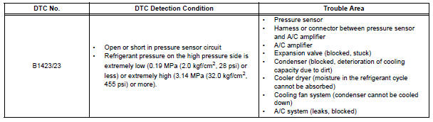
DTC B1423/23 Pressure Sensor Circuit
DESCRIPTION
This DTC is output when refrigerant pressure on the high pressure side is
extremely low (0.19 MPa (2.0
kgf/cm2, 28 psi) or less) or extremely high (3.14 MPa (32.0 kgf/cm2, 455 psi) or
more). The pressure
sensor, which is installed on the pipe of the high pressure side to detect
refrigerant pressure, outputs a
refrigerant pressure signal to the A/C amplifier. The A/C amplifier converts
this signal to pressure
according to the sensor characteristics to control the compressor.
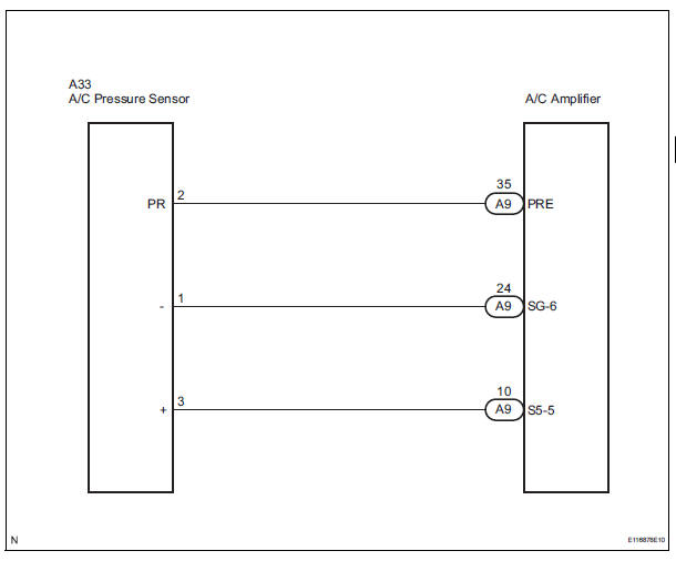
WIRING DIAGRAM
INSPECTION PROCEDURE
1 CHECK HARNESS AND CONNECTOR (POWER SOURCE CIRCUIT)
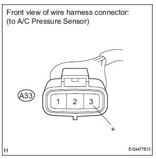
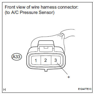
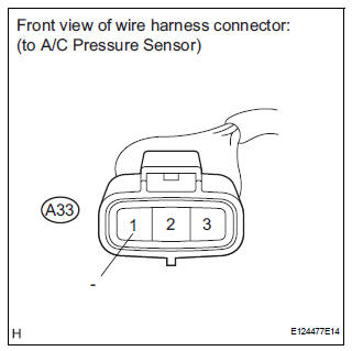
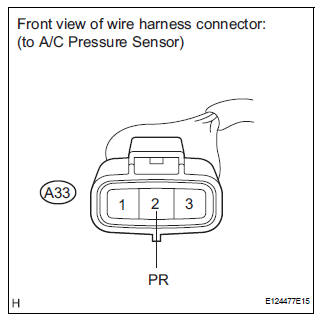
(a) Disconnect the connector from the A/C pressure sensor.
(b) Measure the voltage according to the value(s) in the table below.
Standard voltage 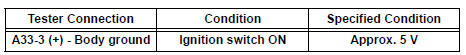

2 CHECK HARNESS AND CONNECTOR (GROUND CIRCUIT)
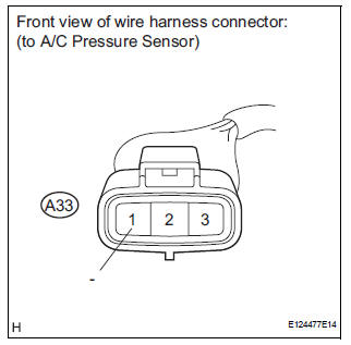
(a) Measure the resistance according to the value(s) in the table below.
Standard resistance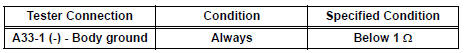

3 INSPECT A/C PRESSURE SENSOR (SENSOR SIGNAL CIRCUIT)
(a) Reconnect the connector to the A/C pressure sensor.
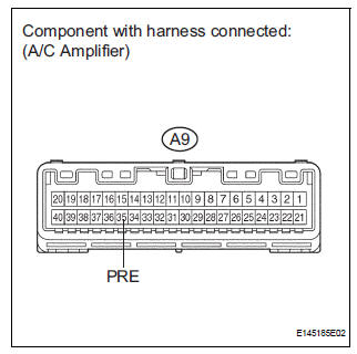
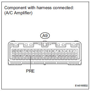
(b) Remove the A/C amplifier with connectors still connected.
(c) Measure the voltage according to the value(s) in the table below.
Standard voltage 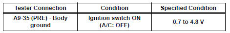
HINT: If the measured voltage is not within the normal range, there may be a malfunction in the A/C amplifier, A/C pressure sensor, or wire harness. It is also possible that the amount of refrigerant may not be appropriate.

4 INSPECT A/C PRESSURE SENSOR (SENSOR SIGNAL CIRCUIT)
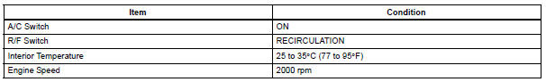
(a) Measure the voltage when the following conditions are
satisfied. 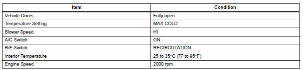
NOTICE:
- If refrigerant pressure on the high pressure side becomes extremely high during the inspection (if the voltage exceeds 4.8 V), the fail-safe function stops compressor operation. Therefore, measure the voltage before the fail-safe operation.
- It is necessary to measure the voltage for a certain amount of time (approximately 10 minutes) because the problem symptom may recur after a while.
HINT: When the outside air temperature is low (below -1.5°C (29.3°F)), the compressor stops due to operation of the ambient temperature sensor and the evaporator temperature sensor to prevent the evaporator from freezing. In this case, perform the inspection in a warm indoor environment.
(1) Measure the voltage according to the value(s) in the table below.
Standard voltage 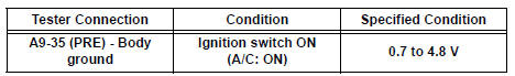
Result 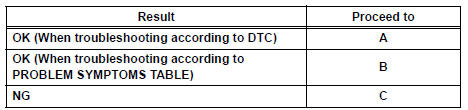
REPLACE A/C AMPLIFIER
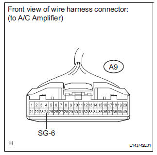
5 CHECK HARNESS AND CONNECTOR (A/C AMPLIFIER - A/C PRESSURE SENSOR)
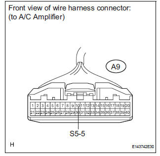
(a) Disconnect the connector from the A/C amplifier.
(b) Measure the resistance according to the value(s) in the table below.
Standard resistance 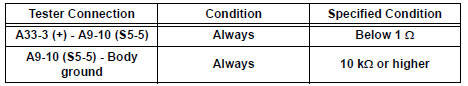

REPLACE A/C AMPLIFIER
6 CHECK HARNESS AND CONNECTOR (A/C AMPLIFIER - A/C PRESSURE SENSOR)
(a) Disconnect the connector from the A/C amplifier.
(b) Measure the resistance according to the value(s) in the table below.
Standard resistance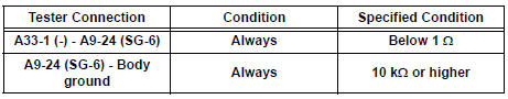
REPLACE A/C AMPLIFIER
7 CHECK HARNESS AND CONNECTOR (A/C AMPLIFIER - A/C PRESSURE SENSOR)
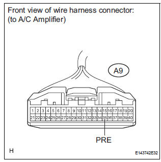
(a) Disconnect the connector from the A/C amplifier.
(b) Measure the resistance according to the value(s) in the table below.
Standard resistance 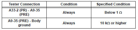

8 CHECK FOR A/C SYSTEM LEAK
(a) Install the manifold gauge set.
(b) Recover the refrigerant from the A/C system using a refrigerant recovery unit.
(c) Evacuate the A/C system and check that vacuum can be maintained in it.
OK: Vacuum can be maintained in the A/C system.
HINT: If vacuum cannot be maintained in the A/C system, refrigerant may be leaking from it. In this case, it is necessary to repair or replace the leaking part of the A/C system.

9 CHARGE REFRIGERANT
(a) Add an appropriate amount of refrigerant (See page AC- 173).

10 RECHECK DTC
(a) Recheck for the DTC when the following conditions are
satisfied.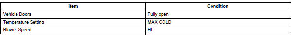
NOTICE: If refrigerant pressure on the high pressure side becomes high, the DTC will be set. It is necessary to measure the voltage for a certain amount of time (approximately 10 minutes) because the DTC may be set after the A/C operates for a while.
HINT: When the outside air temperature is low (below -1.5°C (29.3°F)), the compressor stops due to operation of the ambient temperature sensor and the evaporator temperature sensor to prevent the evaporator from freezing. In this case, perform the inspection in a warm indoor environment.
Result 
NOTICE: If the DTC was set due to an insufficient or excessive amount of refrigerant, the problem may have been solved after performing the previous step. However, the root cause of insufficient refrigerant may be refrigerant leaks. The root cause of excessive refrigerant may be adding refrigerant when the level was insufficient. Therefore, identify and repair the area where refrigerant leaks from as necessary.


11 INSPECT A/C PRESSURE SENSOR
(a) Install the manifold gauge set.
(b) Disconnect the connector from the A/C pressure sensor.
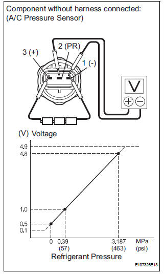
(c) Connect the three 1.5 V dry cell batteries' positive (+) lead to terminal 3, and the negative (-) lead to terminal 1.
(d) Connect the voltmeter's positive (+) lead to terminal 2, and the negative (-) lead to terminal 1.
(e) Measure the voltage according to the value(s) in the table below.
Standard voltage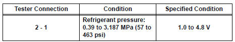
REPLACE A/C AMPLIFIER
12 REPAIR A/C SYSTEM LEAK
(a) Identify the area where refrigerant leaks from (See page AC-173).
(b) Repair the identified area of the A/C system.
(c) Evacuate the A/C system.

CHARGE REFRIGERANT (See page AC-173)
13 INSPECT COOLING FAN SYSTEM
(a) Check if the cooling fan operates normally (See page CO-4).


14 CHARGE REFRIGERANT
(a) Use a refrigerant recovery unit to recover refrigerant.
(b) Evacuate the A/C system.
(c) Add an appropriate amount of refrigerant (See page AC- 173).
HINT: If refrigerant is added and the system has not been properly evacuated (insufficient vacuum time), moisture in the air remaining in the system will freeze in the expansion valve, blocking the flow on the high pressure side. Therefore, in order to confirm the problem, recover the refrigerant and properly evacuate the system. Add an appropriate amount of refrigerant, and check for the DTC.

15 RECHECK DTC
(a) Recheck for the DTC when the following conditions are
satisfied. 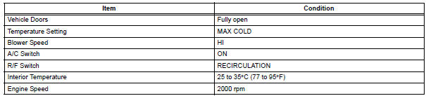
NOTICE: If refrigerant pressure on the high pressure side becomes high, the DTC will be set. It is necessary to measure the voltage for a certain amount of time (approximately 10 minutes) because the DTC may be set after the A/C operates for a while.
HINT:
- When the outside air temperature is low (below -1.5°C (29.3°F)), the compressor stops due to operation of the ambient temperature sensor and the evaporator temperature sensor to prevent the evaporator from freezing. In this case, perform the inspection in a warm indoor environment.
- If refrigerant is added and the system has not been properly evacuated (insufficient vacuum time), moisture in the air remaining in the system will freeze in the expansion valve, blocking the flow on the high pressure side. Therefore, in order to confirm the problem, recover the refrigerant and properly evacuate the system. Add an appropriate amount of refrigerant, and check for the DTC. If the DTC is not output after this work, it indicates that the cooler dryer in the condenser is not able to absorb moisture in the refrigerant cycle. In this case, it is necessary to replace the cooler dryer in order to complete the repair.
Result 


16 REPLACE EXPANSION VALVE
(a) Replace the expansion valve with a normal one (See page AC-186).
HINT: Replace the expansion valve with a normal one because the expansion valve is either stuck or clogged.

17 CHARGE REFRIGERANT
(a) Add an appropriate amount of refrigerant (See page AC- 173).

18 RECHECK DTC
(a) Recheck for the DTC when the following conditions are
satisfied.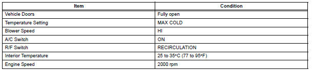
NOTICE: If refrigerant pressure on the high pressure side becomes high, the DTC will be set. It is necessary to measure the voltage for a certain amount of time (approximately 10 minutes) because the DTC may be set after the A/C operates for a while.
HINT:
- When the outside air temperature is low (below -1.5°C (29.3°F)), the compressor stops due to operation of the ambient temperature sensor and the evaporator temperature sensor to prevent the evaporator from freezing. In this case, perform the inspection in a warm indoor environment.
- If refrigerant pressure is not normal after replacing the expansion valve with a normal one, the condenser or pipes may be clogged due to dirt, dust or other contaminant. In this case, clean or replace the condenser or pipes.
Result 

END
 Compressor Lock Sensor Circuit
DTC B1422/22 Compressor Lock Sensor Circuit
SYSTEM DESCRIPTION
The ECM sends an engine speed signal to the A/C amplifier via CAN
communication and BEAN
communication.
The A/C amplifier reads t ...
 Solar Sensor Circuit (Driver Side)
DESCRIPTION
The solar sensor, which is installed on the upper side of the instrument
panel, detects sunlight and
controls the air conditioning in AUTO mode. The output voltage from the solar
...
Other materials:
Park / Neutral Position Switch Circuit
DESCRIPTION
The clearance warning ECU receives the reverse or park position signal from
the park / neutral position
switch.
WIRING DIAGRAM
INSPECTION PROCEDURE
1 INSPECT CLEARANCE WARNING ECU
Disconnect the C9 connector from the clearance warning
ECU.
Measure the voltage ...
Side Airbag Sensor Assembly RH Circuit Malfunction
DTC B1140/32 Side Airbag Sensor Assembly RH Circuit Malfunction
DESCRIPTION
The side airbag sensor RH circuit consists of the center airbag sensor
assembly and side airbag sensor
RH.
If the center airbag sensor assembly receives signals from the side airbag
sensor RH, it judges whether or
...
Data list / active test
1. USING INTELLIGENT TESTER
Connect the intelligent tester to the DLC3.
Monitor the ECU data by following the prompts on
the tester screen.
HINT:
The intelligent tester has a "Snapshot" function
which records the monitored data. Refer to the
intelligent tester ope ...
