Toyota Sienna Service Manual: Data list / active test
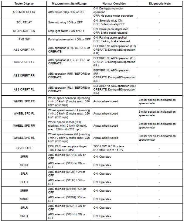
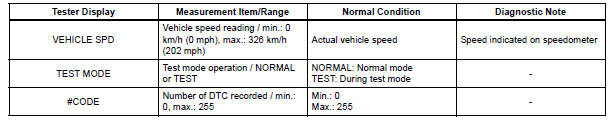
1. DATA LIST
(a) While the intelligent tester is connected to the DLC3 with the ignition switch in the ON position, the ABS data list can be displayed. Follow the prompts on the tester screen to access the DATA LIST.
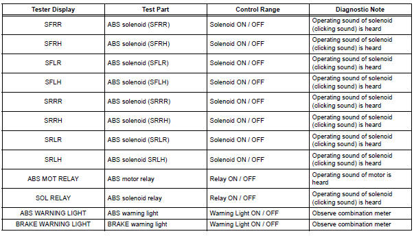
2. ACTIVE TEST
HINT: Performing the ACTIVE TEST using the intelligent tester allows the relay, actuator, etc. to operate without removing any parts. Performing the ACTIVE TEST as the first step of troubleshooting is one of the methods to shorten labor time.
It is possible to display the DATA LIST during the ACTIVE TEST.
(a) Connect the intelligent tester to the DLC3.
(b) Turn the ignition switch to the ON position.
(c) According to the display on the tester, perform the ACTIVE TEST.
HINT: The ignition switch must be turned to the ON position to proceed to the ACTIVE TEST using the intelligent tester.
 Freeze frame data
1. FREEZE FRAME DATA
(a) Whenever a DTC is detected or the ABS operates,
the skid control ECU stores the current vehicle
(sensor) state as freeze frame data.
The skid control ECU stores the numb ...
 Diagnostic trouble code chart
HINT:
If a trouble code is displayed during the DTC check, check
the circuit indicated by the DTC. For details of each code,
turn to the page for the respective DTC Code. in the DTC
chart.
...
Other materials:
Removal
1. REMOVE ENGINE AND TRANSAXLE
HINT:
(See page EM-26)
2. REMOVE AUTOMATIC TRANSMISSION WITH
TRANSFER
HINT:
(See page AX-164)
3. REMOVE TRANSFER ASSEMBLY
HINT:
(See page TF-8)
4. REMOVE CTR DIFFERENTIAL LOCK SLEEVE
HINT:
(See page TF-13)
5. REMOVE TRANSFER CASE OIL SEAL
(a) Using SS ...
Diagnosis system
1. BUS CHECK
Select "BUS CHECK" from the "OBD/MOBD
MENU" screen.
HINT:
The ECUs and sensors that are properly connected
to the CAN communication system can be displayed
using the intelligent tester via the CAN VIM.
Press "ENTER" on the intelligent te ...
Diagnostic trouble code chart
If a malfunction code is displayed during the DTC check,
check the circuit listed for that code in the table below.
(Proceed to the page given for that circuit.)
POWER BACK DOOR SYSTEM
DTC No.
Detection Item
Trouble Area
B2222
PBD Pulse Sensor Malfuncti ...
