Toyota Sienna Service Manual: Data list / active test
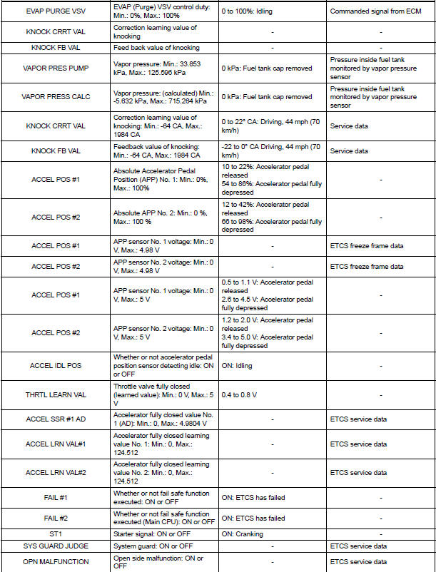
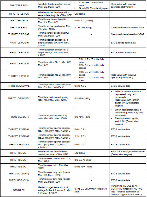
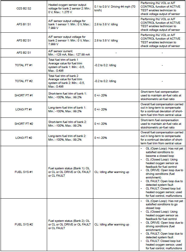
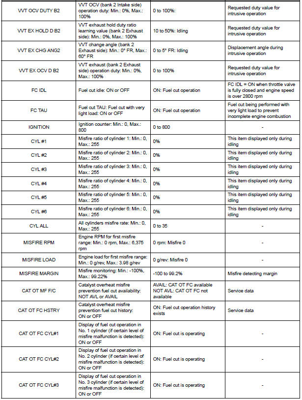
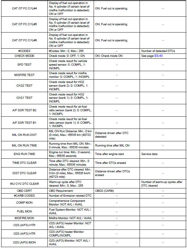
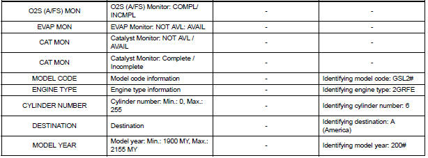
1. DATA LIST
HINT: Reading the DATA LIST displayed on an intelligent tester enables values, including those of the switches, sensors, and actuators, to be checked without removing any parts. Reading the DATA LIST as the first step in troubleshooting is one method to shorten diagnostic time.
NOTICE: In the table below, the values listed under Normal Condition are for reference only. Do not depend solely on these values when determining whether or not a part is faulty.
- Warm up the engine.
- Turn the ignition switch off.
- Connect an intelligent tester to the DLC3.
- Start the engine.
- Turn the tester ON.
- Select the following menu items: DIAGNOSIS / ENHANCED OBD II / DATA LIST.
- Check the values by referring to the table below.
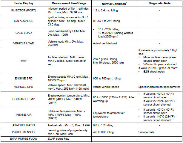
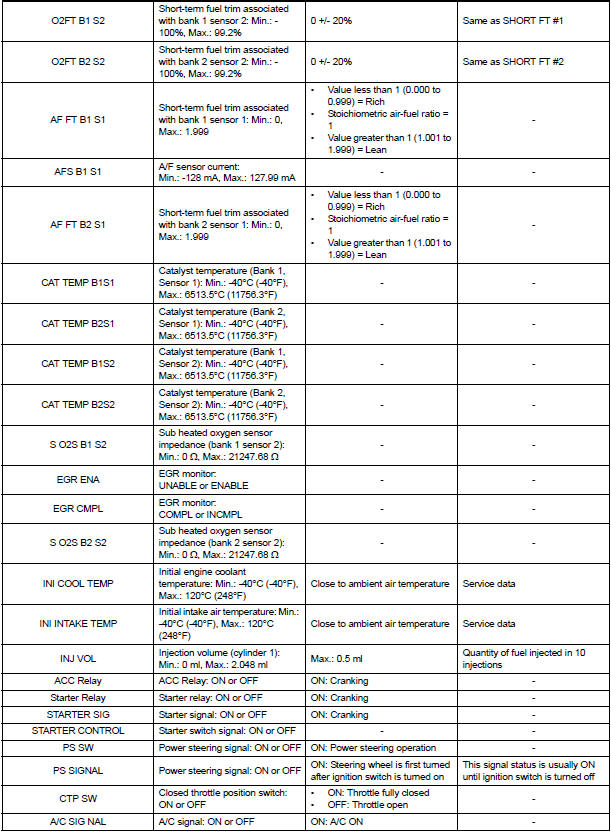
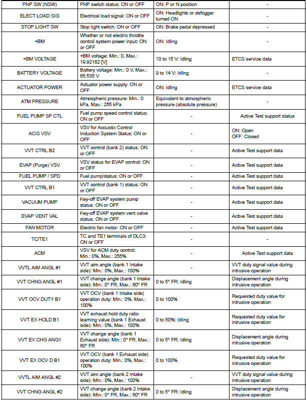
*: If no idling conditions are specified, the transmission gear selector lever should be in the N or P position, and the A/C switch and all accessory switches should be OFF.
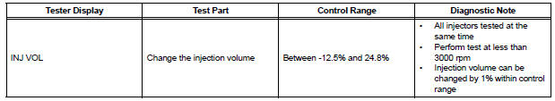
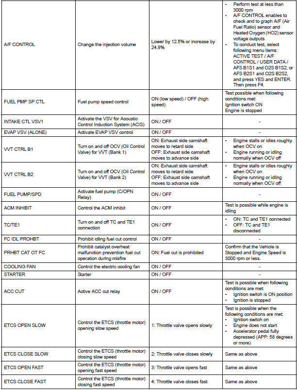
2. ACTIVE TEST
HINT: Performing an ACTIVE TEST enables components including the relays, VSV (Vacuum Switching Valve), and actuators, to be operated without removing any parts.
The ACTIVE TEST can be performed with an intelligent tester. Performing an ACTIVE TEST in the first step in troubleshooting is one method to shorten diagnostic time.
DATA LIST can be displayed during ACTIVE TESTs.
- Connect an intelligent tester to the DLC3.
- Start the engine.
- Turn the tester ON.
- Select the following menu items: DIAGNOSIS / ENHANCED OBD II / ACTIVE TEST.
- Perform the ACTIVE TEST by referring to the table below.
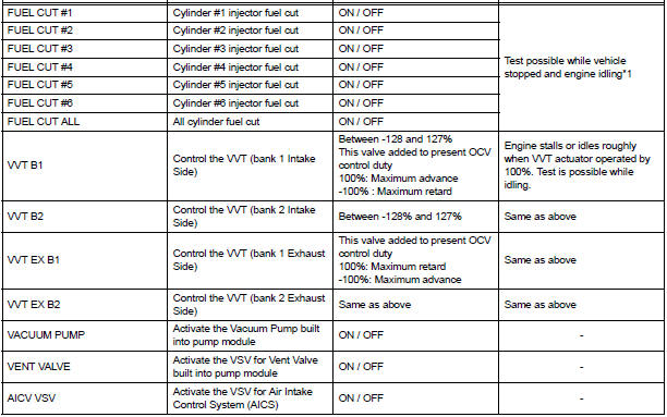
NOTICE:
- *1: If the display of the DATA LIST's CAT OT MF F/C item is NOT AVL, perform this ACTIVE TEST with the vehicle stopped and the engine idling.
- *1: If the display of the DATA LIST's CAT OT MF F/C item is AVAIL, perform this ACTIVE TEST as described below.
- Stop the engine and turn the ignition switch ON to turn FUEL CUT#1 (to #6) ON.
- Start the engine.
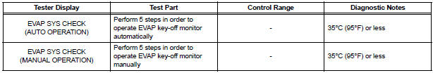
3. SYSTEM CHECK
HINT: Performing a SYSTEM CHECK enables the system, which consists of the multiple actuators, to be operated without removing any parts. In addition, it can show whether or not any DTCs are set, and can detect potential malfunctions in the system. The SYSTEM CHECK can be performed with an intelligent tester.
- Connect an intelligent tester to the DLC3.
- Start the engine.
- Turn the tester ON.
- Select the following menu items: DIAGNOSIS / ENHANCED OBD II / SYSTEM CHECK.
- Perform the SYSTEM CHECK by referring to the table below.
 Fail-safe chart
If any of the following DTCs are set, the ECM enters fail-safe
mode to allow the vehicle to be driven temporarily.
HINT:
*1: The vehicle can be driven slowly when the accelerator
ped ...
 Diagnostic trouble code chart
HINT:
The parameters listed in the chart may not confirm exactly to
those read during the DTC check due to the type of
instrument or other factors.
If a trouble code is displayed during the DTC ...
Other materials:
Terminals of ECU
1. CLEARANCE WARNING ECU
*1: with Front Clearance Sonar
2. AIR CONDITIONER AMPLIFIER ASSEMBLY
*1: with Front Clearance Sonar
*2: Manual A/C
*3: Auto A/C
Reference: waveform 1
HINT:
Terminal: CBZ - E, BBZ - E, Z- - Body ground
Gauge set: 2 ...
Display
When the sensors detect an obstacle, the following displays inform
the driver of the position and distance to the obstacle.
Multi-information display
Front corner sensor operation
Rear corner sensor operation
Rear center sensor operation
Audio system screen
Intuitive parking ...
Components
REMOVAL
1. DISCONNECT CABLE FROM NEGATIVE BATTERY
TERMINAL
2. REMOVE FRONT BUMPER ASSEMBLY
3. REMOVE FOG LIGHT ASSEMBLY
Disengage the 2 claws
Disengage the 2 pins and remove the fog light
assembly.
DISASSEMBLY
1. REMOVE FOG LIGHT BULB
Turn in the dir ...
