Toyota Sienna Service Manual: Diagnosis display detailed description
HINT:
- This section contains a detailed description of displays within diagnostic mode.
- Illustrations may differ from the actual vehicle depending on the device settings and options. Therefore, some detailed areas may not be shown exactly the same as on the actual vehicle.
1. SYSTEM CHECK
- System Check Mode Screen
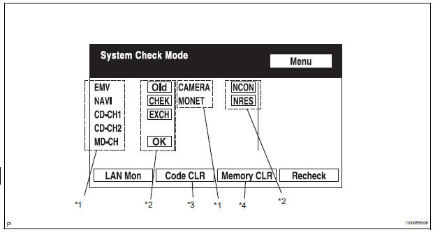
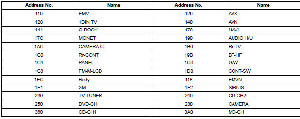
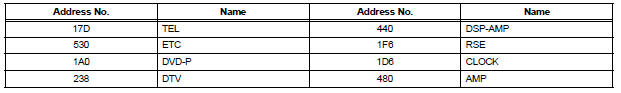
- Device Names and Hardware Address/*1
HINT:
- Registered device names are displayed.
- If a device name is unknown to the system, its physical address is shown instead.
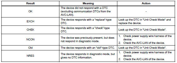
- Check Result/*2
HINT: Result codes for all devices are displayed.
- Code Clear/*3
- Present DTCs are cleared.
- Press the "Code CLR" switch for 3 seconds.
- Memory Clear/*4
- - Present and past DTCs and registered connected device names are cleared.
- Press the "Memory CLR" switch for 3 seconds.
- Diagnosis MENU Screen
HINT: Each item is grayed out or not displayed based on the device settings.
- Unit Check Mode Screen
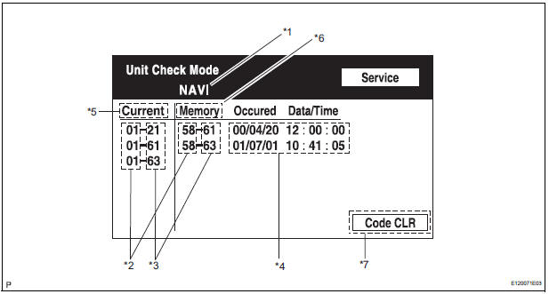
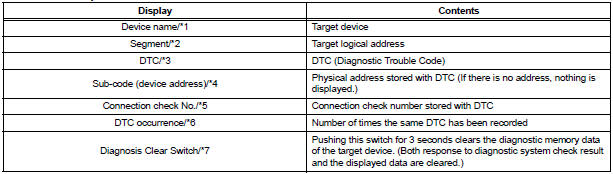
Screen Description:
|
Display |
Contents |
| Device name/*1 | Target device |
| Segment/*2 | Target device logical address |
| DTC/*3 | DTC (Diagnostic Trouble Code) |
| Timestamp/*4 | The time and date of past DTCs are displayed. (The year is displayed in 2-digit format.) |
| Present Code/*5 | DTCs output at the service check are displayed. |
| Past Code/*6 | Diagnostic memory results and recorded DTCs are displayed |
| Diagnosis Clear Switch/*7 | Pushing this switch for 3 seconds clears the diagnostic memory data of the target device. (Both response to diagnostic system check result and the displayed data are cleared.) |
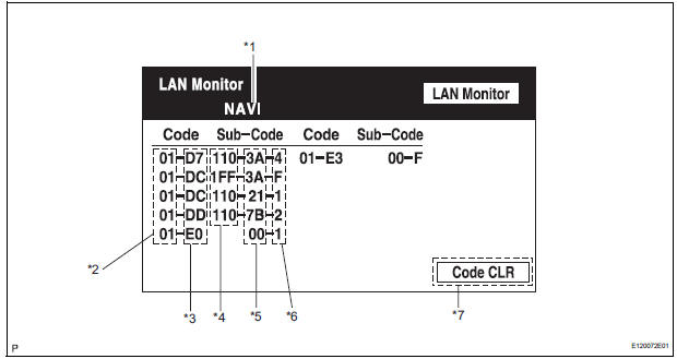
- LAN Monitor (Original) Screen
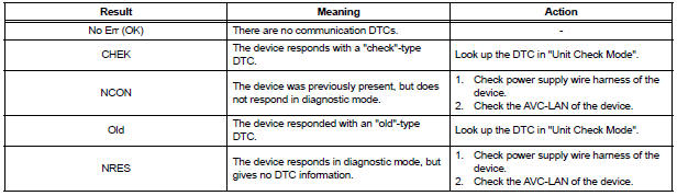
- Check Result/*1
HINT: Check results of all the devices are displayed.
- LAN Monitor (Individual) Screen
Screen Description:
2. DISPLAY CHECK
- Vehicle Signal Check Mode Screen
Screen Description:
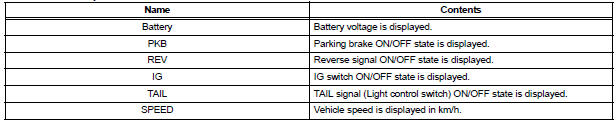
HINT:
- Only items sending a vehicle signal will be displayed.
- This screen is updated once per second when input signals to the vehicle are changed.
- CAN Connection Check Screen
Screen Description:
|
Name |
Contents |
| CAN Connection check result/*1 |
|
HINT:
- This function operates only for the systems connected to the CAN system.
- When the ignition switch is turned off, the bus lines are disconnected, or a malfunction occurs in the bus lines while the CAN connection check result is being displayed, the problem will be reflected on the screen in real time.
HINT: When the ignition switch is turned off, the bus lines are disconnected, or a malfunction occurs in the bus lines while the CAN connection check result is being displayed, the problem will be reflected on the screen in real time
3. NAVIGATION CHECK
- Navigation Check Screen
HINT: Each item is grayed out or not displayed based on the device settings.
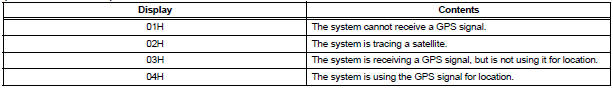
- GPS Information Screen
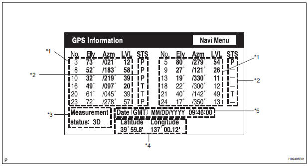
- Satellite information/*1
Information from a maximum of 12 satellites is displayed on the screen. This information includes the target GPS satellite number, elevation angle, direction, and signal level. - Receiving condition/*2
(DENSO model):
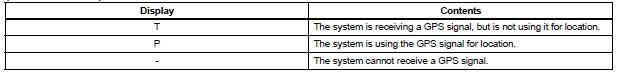
(AISIN AW model):
Measurement information/*3:
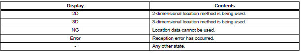
Position information/*4

Date information/*5:

- Vehicle Sensors Screen
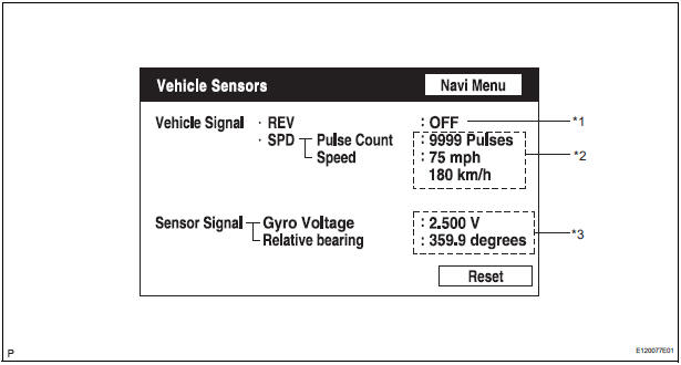
Vehicle signal:

Sensor signal:

HINT: Signals are updated once per second only when vehicle sensor signals are changed.
- Microphone & Voice Recognition Check Screen
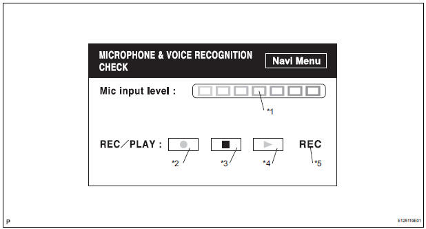
Screen Description:
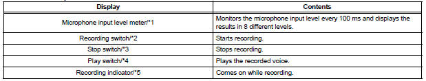
HINT:
- The microphone input function is on at all times when this screen is displayed.
- While recording or playing, the switches other than the stop switch cannot be pushed.
- When no voice is recorded, the play switch cannot be pushed.
- Recording will stop after 5 seconds or by pushing the stop switch.
Screen Description:
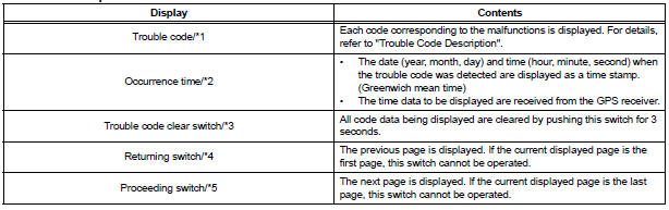
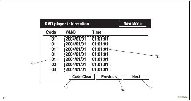
Trouble Code Description:
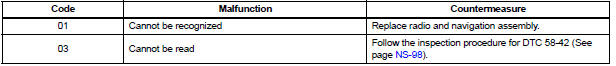
HINT: This is a DVD player check function in the radio and navigation assembly (built-in navigation ECU).
 Navigation check mode
HINT:
This mode displays GPS satellite information.
Illustrations may differ from the actual vehicle depending
on the device settings and options. Therefore, some
detailed areas ...
 Problem symptoms table
HINT:
Before inspecting the suspected areas listed in the table
below, check the fuse and relay.
Before inspecting the suspected areas listed in the table
below, check the DTCs.
...
Other materials:
Freeze frame data
1. DESCRIPTION
(a) The ECM records vehicle and driving condition
information as freeze frame data the moment a DTC
is stored. When troubleshooting, freeze frame data
can be helpful in determining whether the vehicle
was running or stopped, whether the engine was
warmed up or not, whether the a ...
How to proceed with
troubleshooting
HINT:
Use these procedures to troubleshoot the power folding
seat system.
*: Use the intelligent tester.
1 VEHICLE BROUGHT TO WORKSHOP
2 INSPECT BATTERY VOLTAGE
Standard voltage:
10 to 14 V
If the voltage is below 11 V, recharge or replace the battery
before proceeding.
...
Touch screen gestures
Operations are performed by touching the screen directly with your
finger.
Operation method
Outline
Main use
Touch
Quickly touch and
release once.
Changing and selecting
various settings.
Drag*
Touch the screen
with your ...
