Toyota Sienna Service Manual: Navigation check mode
HINT:
- This mode displays GPS satellite information.
- Illustrations may differ from the actual vehicle depending on the device settings and options. Therefore, some detailed areas may not be shown exactly the same as on the actual vehicle.
1. ENTER DIAGNOSTIC MODE ( )
2. NAVIGATION CHECK
- Select "Navigation Check" from the "Diagnosis MENU" screen.
3. GPS INFORMATION
- Select "GPS Information" from the "Navigation Check" screen.
- When GPS information is displayed, check the GPS conditions.
HINT:
- This screen is updated once per second when input signals to the vehicle are changed.
- For details of this function, refer to DIAGNOSIS DISPLAY DETAILED DESCRIPTION.
4. VEHICLE SENSORS
- Select "Vehicle Sensors" from the "Navigation Check" screen.
- Check all the signals and sensors when vehicle signal information is displayed.
HINT:
- This screen is updated once per second when input signals to the vehicle are changed.
- This screen displays vehicle signals input to the built-in navigation ECU.
- For details of this function, refer to DIAGNOSIS DISPLAY DETAILED DESCRIPTION.
5. COLOR BAR CHECK
- Select "Color Bar Check" from the "Navigation Check" screen
- Check each color of the color bar when the "NAVI Color Bar Check" screen is displayed.
HINT:
- Colors will not be displayed full-screen as in "Display Check Mode".
- This screen displays the built-in navigation ECU display color.
6. MEMORY COPY/PASTE CHECK
HINT: This function cannot be used.
7. PARTS INFORMATION
- Select "Parts Information" from the "Navigation Check" screen.
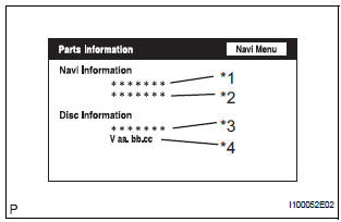
- Check the navigation and disc information when the "Parts Information" screen is displayed.
Screen Description:
|
Display |
Contents |
| Navigation Manufacturer/*1 | Radio and navigation assembly manufacturer is displayed |
| Navigation Version/*2 | Radio and navigation assembly version is displayed. |
| Disc Manufacturer/*3 | Map disc manufacturer is displayed. |
| Disc Version/*4 | Map disc version is displayed. |
8. MIC & VOICE RECOGNITION CHECK
- Select "Mic & Voice Recognition Check" on the "Display Check" screen to display "MICROPHONE & VOICE RECOGNITION CHECK" screen
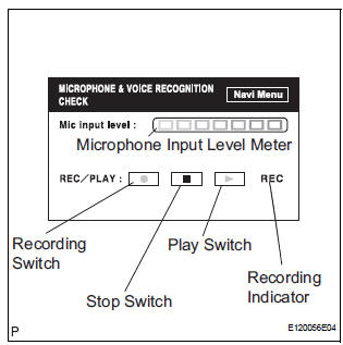
- When voice is input into the microphone, check that the microphone input level meter changes according to the input voice.
- Push the recording switch and perform voice recording.
- Check that the recording indicator remains on while recording and that the recorded voice is played normally.
HINT:
- For details of this function, refer to DIAGNOSIS DISPLAY DETAILED DESCRIPTION.
- This function is controlled by the built-in navigation ECU.
9. DVD PLAYER INFORMATION CHECK
- Select "DVD Player Information" from the "Navigation Check" screen.
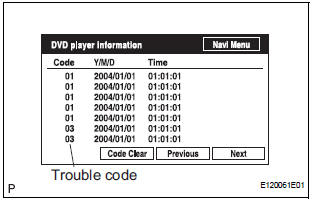
- Check for DTCs.
HINT:
- This is a DVD player check function in the radio and navigation assembly (built-in navigation ECU).
- For details of this function, refer to DIAGNOSIS DISPLAY DETAILED DESCRIPTION.
 Bluetooth tel check mode
HINT:
Illustration may differ from the actual vehicle depending on
the device settings and options. Therefore, some detailed
area may not be shown exactly the same as on the actual
vehicle.
1. EN ...
 Diagnosis display detailed
description
Diagnosis display detailed
description
HINT:
This section contains a detailed description of displays
within diagnostic mode.
Illustrations may differ from the actual vehicle depending
on the device settings and optio ...
Other materials:
Removal
1. DISCHARGE FUEL SYSTEM PRESSURE
HINT:
See page FU-1.
2. DISCONNECT CABLE FROM NEGATIVE BATTERY
TERMINAL
3. REMOVE NO. 1 ENGINE UNDER COVER
4. DRAIN ENGINE COOLANT (See page CO-6)
5. REMOVE FRONT WIPER ARM HEAD CAP (See page
WW-4)
6. REMOVE FRONT WIPER ARM RH (See page WW-4)
7. REMOVE FRO ...
CD Player Mechanical Error/ CD Insertion and Ejection Error/ CD Reading
Abnormal/ CD Changer Mechanical Error/ CD Insertion and Ejection Error/ CD
Reading Abnormal
DTC 62-10 CD Player Mechanical Error
DTC 62-11 CD Insertion and Ejection Error
DTC 62-12 CD Reading Abnormal
DTC 63-10 CD Changer Mechanical Error
DTC 63-11 CD Insertion and Ejection Error
DTC 63-12 CD Reading Abnormal
DESCRIPTION
DTC No.
DTC Detecting Condition
Troub ...
SRS Warning Light does not Come ON
DESCRIPTION
WIRING DIAGRAM
INSPECTION PROCEDURE
1 CHECK BATTERY
Measure the voltage of the battery.
Standard voltage:
11 to 14 V
CHECK AND REPLACE BATTERY OR
CHARGING SYSTEM
2 CHECK CONNECTORS
Turn the ignition switch to the LOCK position.
Disconnect the negative (-) term ...
