Toyota Sienna Service Manual: ECM Power Source Circuit
DESCRIPTION
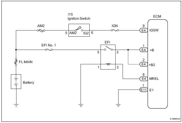
When the ignition switch is turned to the ON position, the battery voltage is applied to terminal IGSW of the ECM. The ECM MREL output signal causes a current to flow to the coil, closing the contacts of the EFI relay and supplying power to terminal +B of the ECM.
If the ignition switch is turned off, the ECM holds the EFI relay ON for a maximum of 2 seconds to allow for the initial setting of the throttle valve.
WIRING DIAGRAM
INSPECTION PROCEDURE
1 INSPECT ECM (+B VOLTAGE)
(a) Turn the ignition switch to the ON position.
(b) Measure the voltage according to the value(s) in the table below.
Standard voltage 

2 CHECK HARNESS AND CONNECTOR (ECM - BODY GROUND)
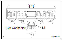
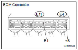
(a) Disconnect the E11 ECM connector.
(b) Measure the resistance according to the value(s) in the table below.
Standard resistance: 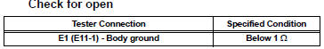
(c) Reconnect the ECM connector.

3 INSPECT ECM (IGSW VOLTAGE)
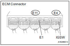
(a) Turn the ignition switch to the ON position.
(b) Measure the voltage according to the value(s) in the table below
Standard voltage 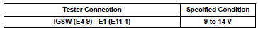

4 CHECK FUSE (IGN FUSE)
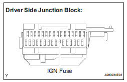
(a) Remove the IGN fuse from the driver side junction block.
(b) Measure the IGN fuse resistance.
Standard resistance: Below 1 Ω
(c) Reinstall the IGN fuse.

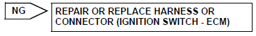
5 CHECK HARNESS AND CONNECTOR (IGNITION SWITCH - ECM)
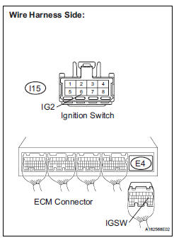
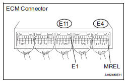
(a) Disconnect the E4 ECM connector.
(b) Disconnect the I15 ignition switch connector.
(c) Measure the resistance according to the value(s) in the table below.
Standard resistance: 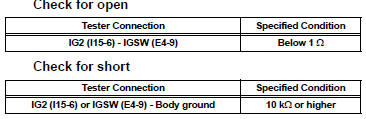
(d) Reconnect the ECM connector.
(e) Reconnect the ignition switch connector.

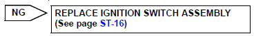
6 INSPECT IGNITION SWITCH ASSEMBLY
(a) Inspect the ignition or starter switch assembly (See page ST-16).

7 CHECK FUSE (AM2 FUSE)
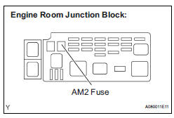
(a) Remove the AM2 fuse from the engine room junction block.
(b) Measure the resistance according to the value(s) in the table below.
Standard resistance: Below 1 Ω
(c) Reinstall the AM2 fuse

REPAIR OR REPLACE HARNESS OR CONNECTOR (IGNITION SWITCH - BATTERY)
8 INSPECT ECM (MREL VOLTAGE)
(a) Turn the ignition switch to the ON position.
(b) Measure the voltage according to the value(s) in the table below.
Standard voltage 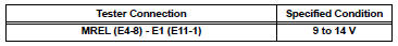

9 CHECK FUSE (EFI NO.1 FUSE)
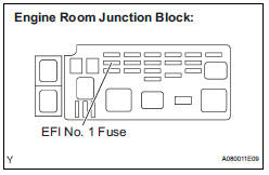
(a) Remove the EFI No. 1 fuse from the engine room junction block.
(b) Measure the EFI No. 1 fuse resistance.
Standard resistance: Below 1 Ω
(c) Reinstall the EFI No. 1 fuse.

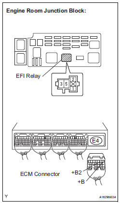
10 INSPECT RELAY (EFI RELAY)
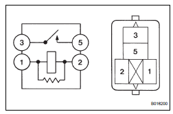
(a) Remove the EFI relay from the engine room junction block.
(b) Measure the EFI relay resistance.
Standard resistance 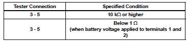
(c) Reinstall the EFI relay.

11 CHECK HARNESS AND CONNECTOR (EFI RELAY - ECM)
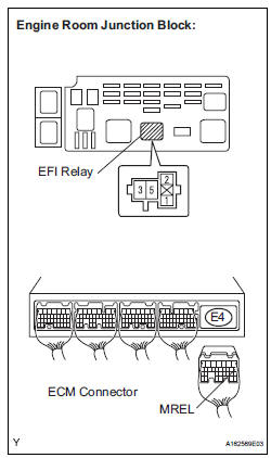
(a) Check the harness and connector between the EFI relay and ECM.
(1) Remove the EFI relay from the engine room junction block.
(2) Disconnect the E4 ECM connector.
(3) Measure the resistance according to the value(s) in the table below.
Standard resistance: 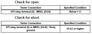

12 CHECK HARNESS AND CONNECTOR (EFI RELAY - ECM)
(a) Remove the EFI relay from the engine room junction block.
(b) Disconnect the E4 ECM connector.
(c) Measure the resistance according to the value(s) in the table below.
Standard resistance: 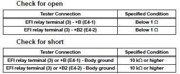
(d) Reinstall the EFI relay.
(e) Reconnect the ECM connector.

13 CHECK HARNESS AND CONNECTOR (EFI RELAY - BODY GROUND)
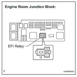
(a) Check the harness and connector between the EFI relay and body ground.
(1) Measure the resistance according to the value(s) in the table below.
Standard resistance : 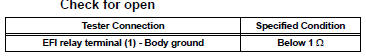
(2) Reinstall the EFI relay.
(3) Reconnect the ECM connector.

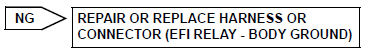
REPAIR OR REPLACE HARNESS OR CONNECTOR (EFI RELAY - BATTERY)
 EVAP System
RELATED DTCS
If any EVAP system DTCs are set, the malfunctioning area can be determined
using the table below.
NOTICE:
If the 0.02 inch reference pressure difference between the ...
 VC Output Circuit
DESCRIPTION
The ECM constantly uses 5 V from the battery voltages supplied to the +B
(BATT) terminal to operate the
microprocessor. The ECM also provides this power to the sensors through the VC
...
Other materials:
Heated oxygen sensor (for 2wd)
Components
Removal
1. DISCONNECT CABLE FROM NEGATIVE BATTERY
TERMINAL
CAUTION:
Wait at least 90 seconds after disconnecting the
cable from the nagative (-) battery terminal to
prevent airbag and seat belt pretensioner activation.
2. REMOVE HEATED OXYGEN SENSOR (for Bank ...
Circuit opening relay
Inspection
1. INSPECT CIRCUIT OPENING RELAY
Using an ohmmeter, measure the resistance
according to the value(s) in the table below.
Standard resistance
If the result is not as specified, replace the relay. ...
Initialization
1. RESET
When the control motor and clutch is replaced:
The power slide door ECU cannot receive a switch
signal from the control motor and clutch. This may
cause the power slide door system to enter fail-safe
mode and DTC (B2224 (LH) or B2223 (RH)) to set,
and also make the syste ...
