Toyota Sienna Service Manual: Disassembly
1. REMOVE REAR SEAT LEG COVER LH
- Remove the 2 screws and seat leg cover.
2. REMOVE REAR SEAT LEG COVER RH
- Remove the 2 screws and seat leg cover.
3. REMOVE REAR SEAT LEG SIDE COVER LH
- Remove the 2 screws and leg side cover.
4. REMOVE LH SEAT REAR SEAT LOCK COVER
- Remove the 2 screws and seat lock cover.
5. REMOVE RH SEAT REAR SEAT LOCK COVER
- Remove the 2 screws and seat lock cover.
6. REMOVE RECLINING ADJUSTER KNOB CAP LH

- Using a screwdriver, disengage the claws and remove the reclining adjuster knob cap.
HINT: Tape the screwdriver tip before use.
7. REMOVE NO. 1 RECLINING ADJUSTER RELEASE HANDLE LH
- Using a screwdriver, disengage the claws and remove the reclining adjuster release handle.
HINT: Tape the screwdriver tip before use.
8. REMOVE REAR SEAT CUSHION SHIELD LH
- Remove the 2 screws.
- Using a screwdriver, disengage the claws and remove the cushion shield.
HINT: Tape the screwdriver tip before use.
9. REMOVE RECLINING ADJUSTER INSIDE COVER LH
- Remove the 3 screws.
- Using a screwdriver, disengage the claws and remove the reclining adjuster inside cover.
HINT: Tape the screwdriver tip before use.
10. REMOVE REAR SEAT RECLINING COVER INNER LH (for 7-Passenger)
- Remove the 2 screws.
- Using a screwdriver, disengage the claws and remove the reclining cover inner.
HINT: Tape the screwdriver tip before use.
11. REMOVE RECLINING ADJUSTER INSIDE COVER LH (for 7-Passenger)
- Remove the screw.
- Using a screwdriver, disengage the claws and remove the reclining adjuster inside cover.
HINT: Tape the screwdriver tip before use.
12. REMOVE REAR SEAT 3 POINT TYPE BELT ASSEMBLY INNER
- Remove the bolt and belt.
13. REMOVE FOLD SEAT STOPPER BAND ASSEMBLY
- Remove the screw and fold seat stopper band.
14. REMOVE REAR NO. 1 SEAT ARMREST ASSEMBLY LH (for 7-Passenger RH Side)
- Using a screwdriver, pry out the armrest No. 1 cap.
HINT: Tape the screwdriver tip before use.
- Remove the bolt and armrest.
15. REMOVE REAR SEAT ARMREST ASSEMBLY RH (for 7-Passenger RH Side)
- Using a screwdriver, pry out the armrest No. 1 cap.
HINT: Tape the screwdriver tip before use.
- Remove the bolt and armrest.
16. REMOVE REAR SEATBACK BOARD LH
- Remove the rear seatback board cap.
- Remove the 2 screws.
- Remove the seatback board by pulling it out in the arrow mark direction shown in the illustration.
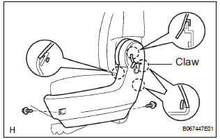
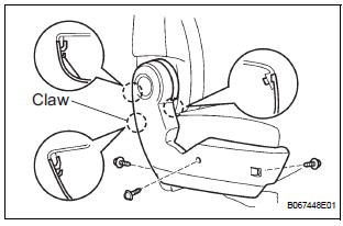
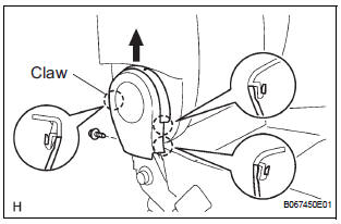
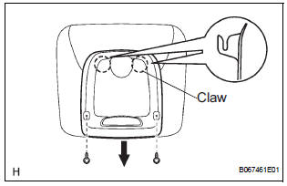
17. REMOVE REAR SEATBACK LOCK BEZEL UPPER
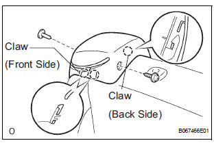
- Remove the clip and screw.
- Using a screwdriver, disengage the front side claws.
HINT: Tape the screwdriver tip before use.
- Apply firm pressure in the directions shown to disengage back side claw and remove the seatback lock bezel upper.
18. REMOVE NO. 1 SEATBACK COVER LH
- Disengage the claw, and remove the 2 headrest supports.
- Remove the hog rings and seatback cover together with the pad.
- Remove the hog rings and seatback cover.
19. REMOVE NO. 1 SEAT CUSHION COVER SUBASSEMBLY LH
- Remove the hog rings between seat cushion cover and cushion frame wire and remove the seat cushion cover together with the pad.
- Remove the hog rings between the seat cushion cover and the pad.
20. REMOVE REAR SEAT SHOULDER BELT COVER RH (for 7-Passenger RH Side)
- Remove the 2 screws and seat shoulder belt cover.
21. REMOVE NO. 1 SEATBACK FRAME SUB-ASSEMBLY
- 7-Passenger RH: Remove the screw and seatback hinge cover.
- 7-Passenger RH: Remove the nut and seat belt retractor.
- Remove the 4 bolts and seatback frame.
22. REMOVE REAR SEAT HINGE COVER LH
- Remove the screw and seat hinge cover.
23. REMOVE NO. 2 REAR SEAT HINGE COVER LH
- Remove the screw and seat hinge cover.
24. REMOVE NO. 1 REAR SEAT ADJUSTER ASSEMBLY INNER LH
- Remove the 2 bolts and seat adjuster.
25. REMOVE RECLINING CONNECTING PIPE LH
26. REMOVE NO. 1 REAR SEAT BELT ASSEMBLY OUTER RH (for 7-Passenger RH Side)
- Remove the 3 nuts and sat belt reclining sensor together with the seat belt.
27. REMOVE REAR SEATBACK ADJUSTER ASSEMBLY OUTER LH
- Disengage the reclining remote control cable.
- Remove the 3 bolts and seatback adjuster.
28. REMOVE REAR SEAT TRACK ADJUSTING HANDLE LH
- Using a screwdriver, disengage the pin and remove the seat track adjusting handle.
HINT: Tape the screwdriver tip before use.
29. REMOVE RECLINING CONTROL LINK SUBASSEMBLY LH
- Remove the nut.
- Remove the E-ring and reclining control link.
30. REMOVE NO. 1 SEAT CUSHION FRAME SUBASSEMBLY LH
- Remove the 5 bolts and seat cushion frame.
 Removal
HINT:
On the RH side, use the same procedures as on the LH side.
1. REMOVE REAR NO. 1 SEAT ASSEMBLY LH
Remove the headrest.
7-Passenger RH:
Remove the bolt and seat belt anchor p ...
 Reassembly
1. INSTALL NO. 1 SEAT CUSHION FRAME SUBASSEMBLY
LH
Install the seat cushion frame with the bolt.
Torque: Except 7-Passenger RH, M8 bolt
20.6 N*m (210 kgf*cm, 15 ft.*lbf)
M10 bolt
41 ...
Other materials:
Inspection
1. INSPECT BRAKE DISC INSIDE DIAMETER
(a) Using a brake drum gauge or equivalent, measure
the inside diameter of the disc.
Standard inside diameter:
190 mm (7.480 in.)
Maximum inside diameter:
191 mm (7.520 in.)
2. INSPECT PARKING BRAKE SHOE LINING THICKNESS
(a) Using a ruler, measur ...
Installing the spare tire
Remove any dirt or foreign matter
from the wheel contact surface.
If foreign matter is on the wheel
contact surface, the wheel nuts
may loosen while the vehicle is in
motion, causing the tire to come
off.
Install the tire and loosely
tighten each wheel nut by hand
by ...
Reassembly
1. INSTALL REAR DOOR WIRE SUB-ASSEMBLY LH
Install the wire.
NOTICE:
When installing the wire, push the areas where
the clips are installed in order to prevent
damage and deformation.
Install the 2 screws.
2. INSTALL REAR DOOR LOCK ASSEMBLY LH
Apply MP grease to the slidi ...
