Toyota Sienna Service Manual: Evaporative Emission System Reference Orifice
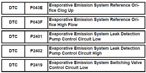
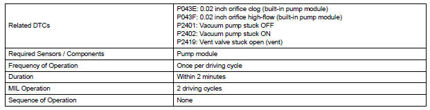
DTC SUMMARY
HINT:
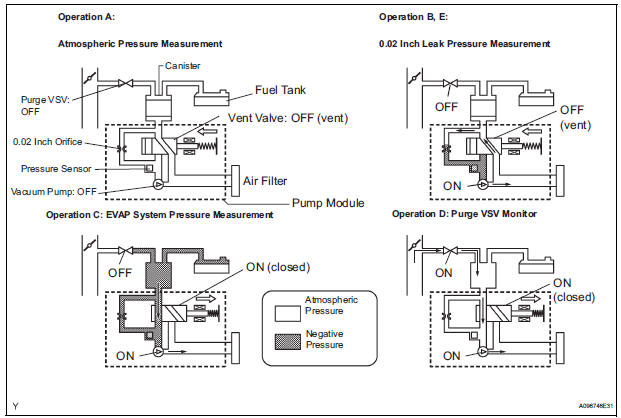
The 0.02 inch orifice is located inside the pump module.
DESCRIPTION
The circuit description can be found in the EVAP (Evaporative Emission) System (See page ES-409).
INSPECTION PROCEDURE
Refer to the EVAP System (See page ES-412).
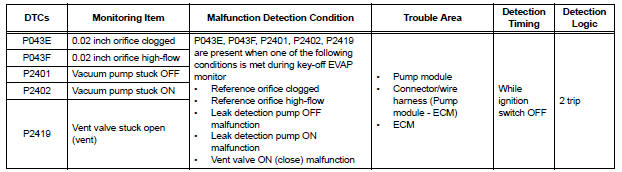
MONITOR DESCRIPTION
5 hours*1 after the ignition switch is turned off, the electric vacuum pump creates negative pressure (vacuum) in the EVAP (Evaporative Emission) system. The ECM monitors for leaks and actuator malfunctions based on the EVAP pressure.
HINT:
*1: If the engine coolant temperature is not below 35°C (95°F) 5 hours after the ignition switch is turned off, the monitor check starts 2 hours later. If it is still not below 35°C (95°F) 7 hours after the ignition switch is turned off, the monitor check starts 2.5 hours later.

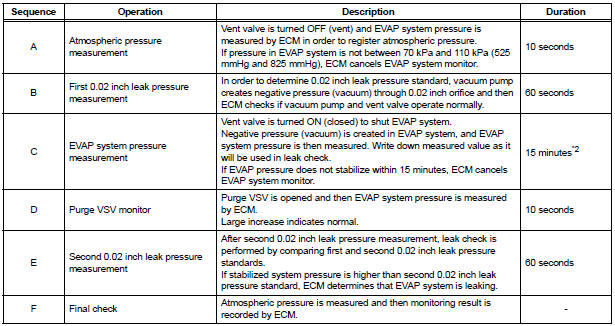
*2: If there is only a small amount of fuel in the fuel tank, stabilizing the EVAP pressure takes longer than usual.
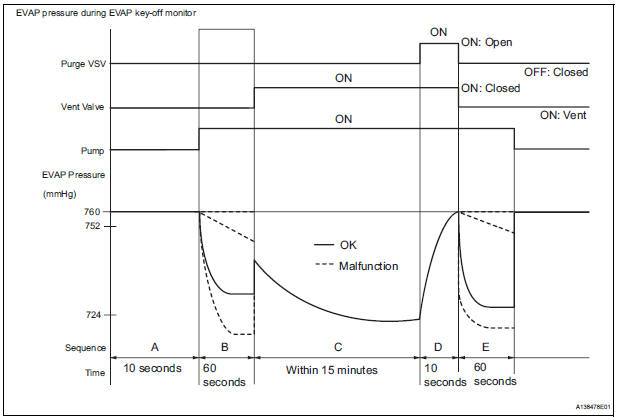
The leak detection pump creates negative pressure through the reference orifice. When the system is normal, the EVAP pressure is in 724 to 752 mmHg* and saturated within a minute.
If not, the ECM interprets this as a malfunction. The ECM will illuminate the MIL and set DTC if this malfunction is detected in consecutive drive cycle.
*: Typical valve
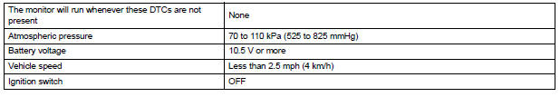
MONITOR STRATEGY
TYPICAL ENABLING CONDITIONS
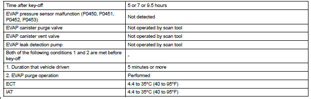
Key-off monitor sequence 1 to 8
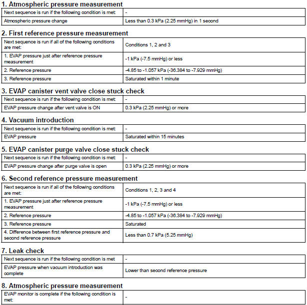

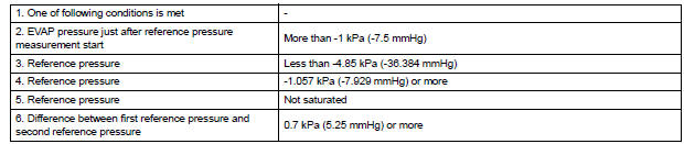
TYPICAL MALFUNCTION THRESHOLDS
MONITOR RESULT
Refer to CHECKING MONITOR STATUS (See page ES-19).
 Catalyst System Efficiency Below Threshold
MONITOR DESCRIPTION
The ECM uses the sensors mounted in front of and behind the three-way
catalyst (TWC) to monitor its
efficiency. The first sensor, an Air Fuel ratio (A/F) sensor, sends pre- ...
 Evaporative Emission Control System Incorrect Purge Flow
DTC SUMMARY
DESCRIPTION
The circuit description can be found in the EVAP (Evaporative Emission)
System (See page ES-409).
INSPECTION PROCEDURE
Refer to the EVAP System (See page ES-412).
MO ...
Other materials:
Installation
1. INSTALL REAR DOOR WINDOW FRAME MOULDING
Remove the tape from the rear door window frame
moulding.
Clean the contact surface of the vehicle body with
white gasoline.
Clean the outer circumference of the rear door
window frame moulding with white gasoline.
Apply new double-sided ...
Short to GND in Curtain Shield Squib RH Circuit
DTC B1162/81 Short to GND in Curtain Shield Squib RH Circuit
DESCRIPTION
The curtain shield squib RH circuit consists of the center airbag sensor
assembly and the curtain shield
airbag assembly RH.
The circuit instructs the SRS to deploy when deployment conditions are met.
DTC B1162/81 is ...
Power slide door control switch
INSPECTION
1. INSPECT POWER SLIDE DOOR CONTROL SWITCH
Inspect the resistance of the switch for LH / RH.
Resistance
If the result is not as specified, replace the switch.
Apply battery voltage and check the illuminates.
Standard
If the result is not as specified, replace the ...
