Toyota Sienna Service Manual: Removal
HINT: On the RH side, use the same procedures as on the LH side.
1. REMOVE SLIDE DOOR
- Remove the rear door scuff plate (See page IR-7).
- Remove the back door scuff plate (See page ED- 214).
- Remove the quarter trim panel (See page IR-9).
- Remove the upper rail cushion from the rail upper.
- Disconnect the 2 connectors from the body side and remove the bolt and wire.
- Open the quarter glass.
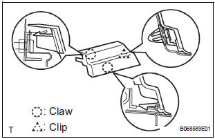
- Using a screwdriver, disengage the clip and 2 claws, remove the rail end moulding.
HINT: Tape the screwdriver tip before use.
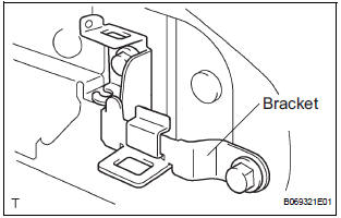
- Remove the 2 bolts and bracket center No. 2.
- Remove the 2 nuts and open stop.
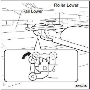
- Rotate the base of the slide door roller lower in the direction indicated by arrow in the illustration and then remove the roller from the cut area of the lower rail from the body side.
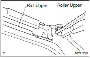
- Move the slide door rearward and then remove the slide door roller upper from the cut area in the rear part of the slide door rail upper.
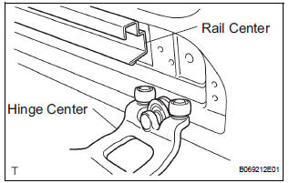
- Move the slide door further rearward and then remove the slide door hinge center from the rear part of the slide door rail center. Then, remove the slide door.
2. REMOVE SLIDE DOOR RAILS
- Remove the roof headlining (See page IR-6).
- Remove the 2 bolts, 2 nuts and the rail upper.
- Remove the 2 screws and the rear side rail.
- Remove the 3 screws and the rail center.
3. REMOVE SLIDE DOOR FULL OPEN STOP LOCK ASSEMBLY LH
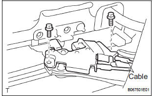
- Disconnect the 2 cables.
- Remove the 2 bolts and lock
4. REMOVE SLIDE DOOR ROLLER ASSEMBLY LOWER LH
- Remove the 3 bolts and roller.
5. REMOVE SLIDE DOOR HINGE ASSEMBLY CENTER LH
- Remove the 3 bolts and hinge.
- LH side: Remove the cover.
6. REMOVE SLIDE DOOR ROLLER ASSEMBLY UPPER
- Remove the 2 bolts and roller.
7. REPLACE SLIDE DOOR HALF OPEN STOPPER SUBASSEMBLY
- Using a screwdriver, remove the 2 clips and cover.
HINT: Tape the screwdriver tip before use.
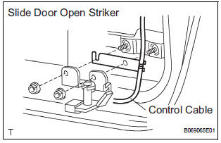
- Remove the 2 bolts and disconnect the control cable from the open striker.
- Disconnect the control cable from the half open stopper.
- Remove the 2 bolts and half open stopper.
8. REPLACE SLIDE DOOR HALF OPEN STOPPER CONTROL ASSEMBLY
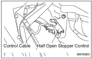
- Remove the 2 nuts and half open stopper control.
- Remove the control cable.
9. REPLACE SLIDE DOOR OPEN STRIKER LH
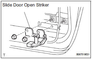
- Remove the 2 nuts and open striker.
10. REPLACE SLIDE DOOR OPEN STRIKER RH
HINT: Use the same procedures for the LH side.
11. REPLACE SLIDE DOOR OPEN STOP LH
- Remove the 2 nuts and open stop.
12. REPLACE SLIDE DOOR OPEN STOP RH
HINT: Use the same procedures for the LH side.
 Slide door
COMPONENTS
...
 Disassembly
HINT:
On the RH side, use the same procedures as on the LH side.
1. REMOVE REAR DOOR WINDOW FRAME MOULDING
REAR LH (See page ET-30)
2. REMOVE REAR DOOR WINDOW FRAME MOULDING
SUB-ASSEMBLY LH (See ...
Other materials:
On-vehicle inspection
1. INSPECT FRONT AIRBAG SENSOR (VEHICLE NOT
INVOLVED IN COLLISION)
Perform a diagnostic system check.
2. INSPECT FRONT AIRBAG SENSOR (VEHICLE
INVOLVED IN COLLISION AND AIRBAG HAS NOT
DEPLOYED)
Perform a diagnostic system check.
When the front bumper of the vehicle o ...
Clearance warning ECU
COMPONENTS
REMOVAL
1. REMOVE FRONT DOOR SCUFF PLATE LH
2. REMOVE COWL SIDE TRIM BOARD LH
3. REMOVE INSTRUMENT PANEL FINISH PANEL SUBASSEMBLY LOWER LH
4. REMOVE NO. 1 INSTRUMENT PANEL SAFETY PAD INSERT SUB-ASSEMBLY
5. REMOVE CLEARANCE WARNING ECU
Disconnect each connector.
&nb ...
Installation
1. INSTALL FRONT DOOR WINDOW FRAME MOULDING
Remove the tape from the front door window frame
moulding.
Clean the contact surface of the vehicle body with
white gasoline.
Clean the outer circumference of the front door
window frame moulding with white gasoline.
Apply new double-si ...
