Toyota Sienna Service Manual: Stereo Component Amplifier Communication Error
INSPECTION PROCEDURE
1 IDENTIFY THE COMPONENT SHOWN BY THE SUB-CODE
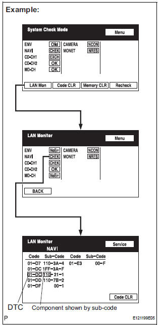
- Enter the diagnostic mode.
- Press the "LAN Mon" switch to change to "LAN Monitor" mode.
- Identify the component shown by the sub-code.
HINT:
- "110 (multi-display)" is the component shown by the sub-code in the example shown in the illustration.
- The sub-code will be indicated by its physical address.
- For the component list, refer to "DIAGNOSIS DISPLAY DETAILED DESCRIPTION".
2 CHECK POWER SOURCE CIRCUIT OF COMPONENT SHOWN BY SUB-CODE
- Inspect the power source circuit of the component shown
by the sub-code.
If the power source circuit is operating normally, proceed to the next step.
Component Table:

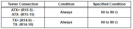
3 CHECK RADIO AND NAVIGATION ASSEMBLY
- Disconnect the radio and navigation assembly connectors.
- Measure the resistance according to the value(s) in the table below.
Standard resistance
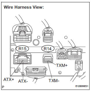
4 CHECK HARNESS AND CONNECTOR (STEREO COMPONENT AMPLIFIER - COMPONENT SHOWN BY SUB-CODE)
HINT:
- Start the check from the circuit that is near the component shown by the sub-code first.
- For details of the connectors, refer to "TERMINALS OF ECU".
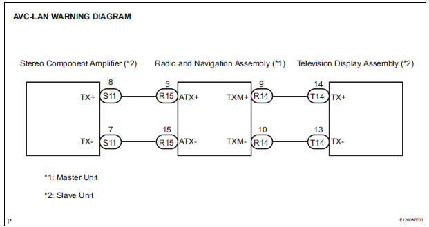
- Referring to the AVC-LAN wiring diagram below, check the AVC-LAN circuit between the stereo component amplifier and the component shown by the sub-code.
- Disconnect all connectors between the stereo component amplifier and the component shown by sub-code.
- Check for an open or short in the AVC-LAN circuit between the stereo component amplifier and the component shown by the sub-code.
OK: There is no open or short circuit.
5 REPLACE COMPONENT SHOWN BY SUB-CODE
- Replace the component shown by the sub-code with a normal one and check if the same problem occurs again.
OK: Same problem does not occur
END
 Microphone Circuit between Microphone and Radio and Navigation
Assembly
Microphone Circuit between Microphone and Radio and Navigation
Assembly
DESCRIPTION
This circuit sends a microphone signal from the microphone to the radio and
navigation assembly.
It also supplies power from the radio and navigation assembly to the microphone.
WIR ...
 Radio and Navigation Assembly Communication Error
INSPECTION PROCEDURE
1 IDENTIFY THE COMPONENT SHOWN BY THE SUB-CODE
Enter the diagnostic mode.
Press the "LAN Mon" switch to change to "LAN Monitor"
mode.
&nbs ...
Other materials:
No Master/ Connection Check Error
DTC 01-D6 No Master
DTC 01-D7 Connection Check Error
DESCRIPTION
HINT:
*1: Even if no fault is present, this trouble code may be stored
depending on the battery condition or
engine start voltage.
*2: When 210 seconds have elapsed after disconnecting the power
supply ...
Checking the messages
Display the message inbox screen.
Select the desired message from the list.
Check that the message is displayed.
E-mails: Select “Mark
Unread” or “Mark Read” to
mark mail unread or read on
the message inbox screen.
This function is available when “Update Read Stat ...
Power Slide Door RH does not Operate When Using Inside / Outside
Handle
DESCRIPTION
The inside / outside handles have the ability to control operation
of the power slide door. Pulling either
handle transmits a request signal to the power slide door ECU RH, which then
commands the power
slide door control motor and clutch to open / close the power sli ...
