Toyota Sienna Service Manual: Internal Control Module Random Access Memory (RAM) Error
DTC P0604 Internal Control Module Random Access Memory (RAM) Error
DESCRIPTION
The ECM continuously monitors its own internal memory status, internal circuits, and output signals transmitted to the throttle actuator. This self-check ensures that the ECM is functioning properly. If any malfunction is detected, the ECM sets the appropriate DTC and illuminates the MIL.
The ECM memory status is diagnosed by internal mirroring of the main CPU and the sub CPU to detect Random Access Memory (RAM) errors. The two CPUs also perform continuous mutual monitoring. The ECM illuminates the MIL and sets a DTC if: 1) outputs from the two CPUs are different or deviate from the standards, 2) the signals sent to the throttle actuator deviate from the standards, 3) a malfunction is found in the throttle actuator supply voltage, and 4) any other ECM malfunction is found.

MONITOR STRATEGY
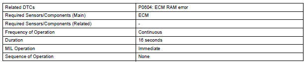
TYPICAL ENABLING CONDITIONS

TYPICAL MALFUNCTION THRESHOLDS
ECM RAM errors:

INSPECTION PROCEDURE
Read freeze frame data using the intelligent tester. Freeze frame data records the engine condition when malfunctions are detected. When troubleshooting, freeze frame data can help determine if the vehicle was moving or stationary, if the engine was warmed up or not, if the air-fuel ratio was lean or rich, and other data from the time the malfunction occurred.
1 CHECK ANY OTHER DTCS OUTPUT (IN ADDITION TO DTC P0604)
- Connect the intelligent tester to the DLC3.
- Turn the ignition switch to the ON position.
- Turn the tester on.
- Select the following menu items: DIAGNOSIS / ENHANCED OBD II / DTC INFO / CURRENT CODES.
- Read DTCs.
Result

REPLACE ECM
 System Voltage
DTC P0560 System Voltage
MONITOR DESCRIPTION
The battery supplies electricity to the ECM even when the ignition switch is
off. This power allows the
ECM to store data such as DTC history, freeze ...
 ECM / PCM Processor
DTC P0606 ECM / PCM Processor
DESCRIPTION
The ECM continuously monitors its internal processors (CPUs), A/F sensor
transistors and heated oxygen
sensor (HO2S) transistors. This self-check ensures ...
Other materials:
Short in Rear Curtain Shield Squib LH Circuit
DTC B1635/87 Short in Rear Curtain Shield Squib LH Circuit
DESCRIPTION
The rear curtain shield squib LH circuit consists of the center airbag sensor
assembly and the curtain
shield airbag assembly LH.
The circuit instructs the SRS to deploy when deployment conditions are met.
DTC B1635/87 ...
Receiving a message
When an e-mail/SMS/MMS is received, the incoming message screen
pops up with sound and is ready to be operated on the screen.
Select to check the message.
Select to refuse the message.
Select to call the message
sender.
Receiving a message
Depending on the cellular phone used f ...
Evaporative Emission System
DTC P043E Evaporative Emission System Reference Orifice
Clog Up
DTC P043F Evaporative Emission System Reference Orifice
High Flow
DTC P2401 Evaporative Emission System Leak Detection
Pump Control Circuit Low
DTC P2402 Evaporative Emission System Leak Detection
Pump Control Circuit High
DTC P ...
